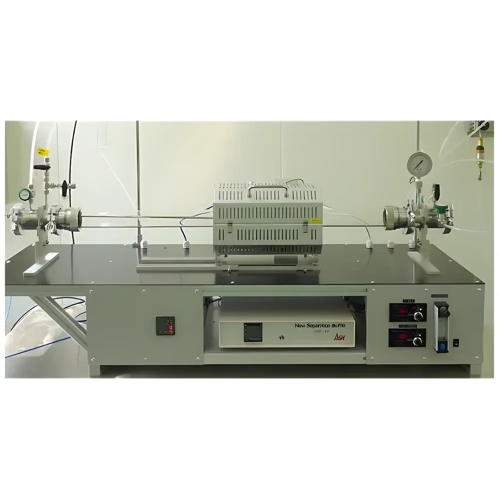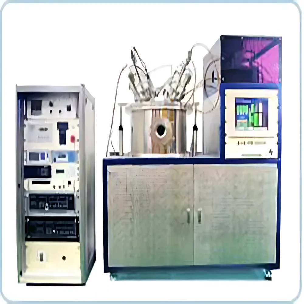
Microphase Model 15 Magnetron Sputtering System

| Brand | Microphase |
|---|---|
| Origin | Japan |
| Model | 15 |
| Vacuum Chamber Options | Cylindrical (φ300–2000 mm) or Custom Rectangular |
| Cathode Materials | OFHC Copper |
| Magnet Type | NdFeB Permanent Magnets (Fixed or Scanning) |
| Sputter Gun Configurations | Circular (1–13 inch), Rectangular (1.5–10 inch width, 5–120 inch length) |
| Power Supplies | DC (1–20 kW), MF (1–20 kW), RF (0.3–15 kW) |
| Substrate Size Range | 2–120 inch |
| Film Uniformity | ±1.5% (scanning magnet), ±3.0% (fixed magnet) |
| Thickness Monitoring | Quartz Crystal Microbalance (QCM) — single/dual/six-sensor configuration |
| Vacuum System | Dry Roughing Pump + Turbomolecular Pump / Cryopump / Ion Gauge |
| Control Architecture | PLC + Industrial Touchscreen PC with IC-5/PC-based Deposition Logic |
| Compliance Ready | GLP/GMP audit trail support, ASTM F2627-compliant process logging |
Ask about pricing, availability and specifications.
Overview
The Microphase Model 15 Magnetron Sputtering System is a high-precision, modular thin-film deposition platform engineered for reproducible physical vapor deposition (PVD) under ultra-high vacuum (UHV) and high-vacuum conditions. Based on the principles of magnetron sputtering—where a plasma discharge is confined near a target surface by crossed electric and magnetic fields—the system enables controlled ejection of atoms from conductive or semi-conductive targets onto substrates via momentum transfer. This physics-driven process ensures atomic-level stoichiometric fidelity in compound film growth (e.g., ITO, SiO₂, TiN, Al₂O₃) and supports both DC, medium-frequency (MF), and radio-frequency (RF) excitation modes for broad material compatibility. Designed for research laboratories, pilot-line R&D, and pre-production environments, the Model 15 integrates vacuum architecture, power delivery, real-time thickness metrology, and programmable process logic into a single robust platform compliant with international thin-film fabrication standards.
Key Features
- Modular cathode configurations: Circular magnetrons (1–13 inch diameter) and planar rectangular magnetrons (1.5–10 inch width, up to 120 inch length for large-area deposition); optional dual-erosion geometry for extended target utilization.
- NdFeB permanent magnet assemblies with fixed or scanning (rotating/linear) magnet configurations—achieving ≤±1.5% thickness uniformity across 12-inch substrates and ≤±3.0% with static field alignment.
- Multi-mode power supply suite: DC (1–20 kW), medium-frequency (1–20 kW), and RF (0.3–15 kW) sources—enabling reactive sputtering, insulator target processing, and in-situ substrate biasing.
- Integrated quartz crystal microbalance (QCM) thickness monitoring with configurable sensor arrays (single, dual, or six-position)—calibrated for real-time deposition rate feedback and endpoint detection.
- UHV-capable chamber architecture: Cylindrical stainless-steel vessel (φ300–2000 mm × 500 mm height) or custom rectangular design; compatible with load-lock modules featuring automated sample transfer and inert-gas purged entry.
- Full-process automation: PLC-driven sequencing with industrial touchscreen HMI; supports manual override, recipe-based execution, and event-triggered parameter adjustment during deposition.
Sample Compatibility & Compliance
The Model 15 accommodates substrates ranging from 2-inch wafers to 120-inch flexible or rigid panels—including glass, silicon, polymer foils, and metal sheets. Its gas handling subsystem employs mass flow controllers (MFCs) for precise Ar, O₂, N₂, and reactive gas dosing, while Baratron capacitance manometers ensure stable pressure regulation during plasma ignition and sustained operation (1×10⁻⁷ Torr base pressure typical). The system meets mechanical and electrical safety requirements per IEC 61000-6-2/6-4 and is configured for traceable operation under GLP and GMP frameworks: all deposition parameters (power, pressure, time, gas flows, QCM readings) are timestamped, logged, and exportable in CSV/Excel format. Optional 21 CFR Part 11-compliant software modules provide electronic signatures, audit trails, and user-access controls for regulated environments.
Software & Data Management
Deposition control is managed via IC-5 and PC-based software architecture, offering hierarchical access levels (operator, engineer, administrator) and scriptable process sequences. Real-time graphs display voltage, current, pressure, deposition rate, and cumulative thickness synchronized to millisecond resolution. All logs include metadata such as chamber ID, operator login, environmental conditions (room temperature/humidity), and calibration status of QCM sensors. Raw data files are stored in vendor-neutral formats (UTF-8 text, HDF5) and can be imported into MATLAB, Python (NumPy/Pandas), or third-party statistical process control (SPC) platforms. Remote diagnostics and firmware updates are supported over secure Ethernet (TLS 1.2), with optional OPC UA integration for factory-wide MES connectivity.
Applications
- Optical coatings: Anti-reflective (AR), high-reflection (HR), and bandpass filters on precision optics and laser components.
- Transparent conductive oxides (TCOs): Uniform ITO, AZO, and GZO films on display substrates for LCD/OLED manufacturing development.
- Hard coatings: CrN, TiAlN, and DLC layers on cutting tools and biomedical implants requiring adhesion testing per ASTM B571.
- Functional thin films: Ferroelectric (PZT), piezoelectric (AlN), and thermoelectric (Bi₂Te₃) layers for MEMS and energy harvesting prototypes.
- Research-grade multilayer stacks: Alternating metal/dielectric structures for plasmonic, photonic crystal, and superconducting device studies.
- Cluster tool integration: Seamless interface with adjacent evaporation, annealing, or etch modules via SECS/GEM protocol.
FAQ
What vacuum level can the Model 15 achieve?
Base pressure of ≤5×10⁻⁸ Torr is attainable with cryopump configuration; standard turbomolecular pump systems reach ≤1×10⁻⁷ Torr after 4-hour bakeout.
Is RF sputtering supported for oxide targets?
Yes—the integrated 0.3–15 kW RF generator enables stable sputtering of Al₂O₃, SiO₂, and other dielectric materials using impedance-matching networks and auto-tuning algorithms.
Can the system be upgraded to in-line configuration?
The Model 15’s modular chamber design and standardized flange interfaces (CF100/CF200) allow direct integration into in-line sputtering lines with conveyor-based substrate transport and inter-chamber isolation valves.
What certifications does the system carry?
CE marking (EMC & LVD directives), RoHS compliance, and ISO 9001-aligned manufacturing documentation are provided; UL/cUL listing available upon request.
How is film uniformity verified and maintained?
Uniformity mapping is performed using witness wafers and profilometry (Dektak) or spectrophotometry (UV-Vis/NIR); magnet scanning profiles and gas distribution manifolds are field-adjustable to compensate for edge effects.