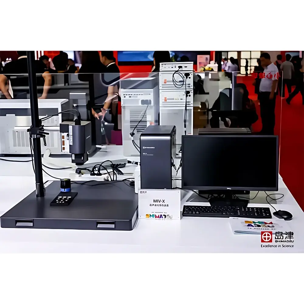
Japanese-imported MIV-X Ultrasonic Optical Imaging Flaw Detector by HG
| Brand | HG |
|---|---|
| Origin | Japan |
| Model | MIV-X |
| Detection Principle | Ultrasonic Excitation + Stroboscopic Laser Imaging |
| Surface Displacement Resolution | Sub-micron (optical) |
| Effective Inspection Depth | Up to ~1 mm |
| Sample Interface Compatibility | Bonded interfaces, thermal spray coatings, paint layers, composite laminates |
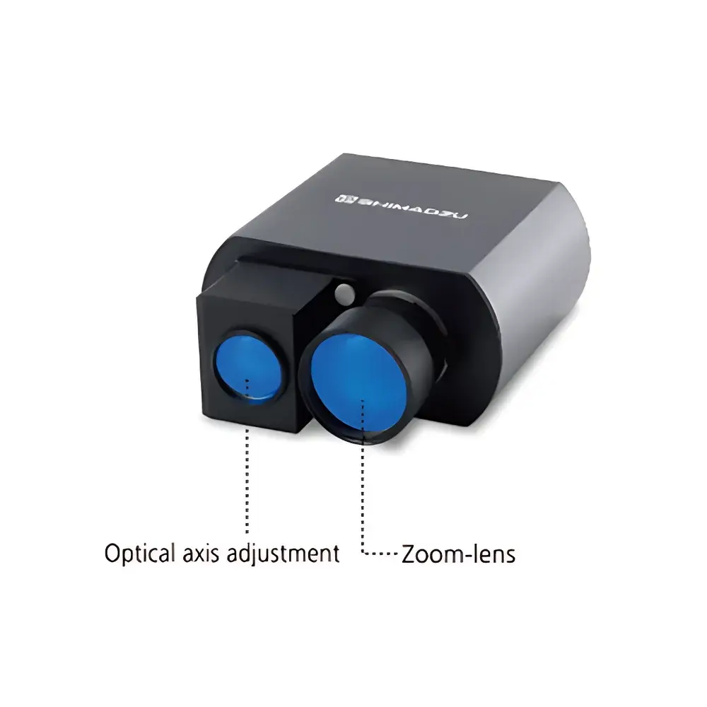
| Optional Accessory | Motorized Optical Zoom Lens Assembly |
| Regulatory Context | Designed for R&D and QC environments compliant with ISO 16840 (Ultrasonic Testing — Characterization of ultrasonic testing equipment), ASTM E2700 (Standard Guide for Acoustic Emission Examination of Fiber Reinforced Polymer Matrix Composites), and GLP-aligned data traceability |
Overview
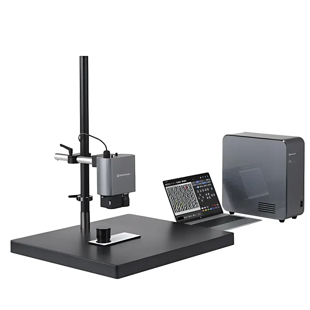
The HG MIV-X Ultrasonic Optical Imaging Flaw Detector is a precision-engineered non-destructive evaluation (NDE) system developed in Japan for high-fidelity visualization of near-surface discontinuities in solid materials. Unlike conventional pulse-echo ultrasonic testing (UT), which relies on acoustic impedance mismatch reflections interpreted via A-scan or C-scan signal analysis, the MIV-X employs a hybrid physical principle: controlled ultrasonic excitation (typically in the 20–100 kHz range) coupled with stroboscopic laser illumination and high-frame-rate optical imaging. When an ultrasonic transducer induces resonant surface vibration in a test specimen, subsurface anomalies—including disbonds, delaminations, micro-cracks, porosity, and coating adhesion failures—alter local wave propagation dynamics. These perturbations manifest as spatially localized deviations in surface displacement amplitude and phase. The MIV-X captures these nanometer-to-micrometer-scale displacements optically using synchronized laser speckle contrast imaging and digital high-speed video acquisition. This enables real-time, full-field, qualitative and semi-quantitative mapping of defect morphology without couplant, scanning mechanics, or signal interpretation expertise.
Key Features
- Stroboscopic laser-optical displacement imaging: Captures dynamic surface motion induced by broadband or swept-frequency ultrasonic excitation with sub-pixel spatial resolution.
- Real-time video-based defect visualization: Eliminates reliance on waveform interpretation; defects appear directly as contrast anomalies in live video feed.
- Non-contact, non-couplant operation: No liquid coupling medium required—ideal for temperature-sensitive, porous, or coated surfaces.
- Intuitive operator interface: Minimal training required; transducer placement and camera alignment follow standardized ergonomic workflows.
- Integrated annotation and measurement suite: On-screen defect marking, length/area quantification, and frame-by-frame playback with timestamped metadata export.
- Modular optical path: Optional motorized zoom lens assembly supports magnification up to 10× for sub-50 µm feature resolution on flat or gently curved surfaces.
Sample Compatibility & Compliance
The MIV-X is validated for use across heterogeneous material systems where interfacial integrity governs performance—particularly adhesive bonds, thermal barrier coatings, polymer matrix composites, multi-layer metal stacks, and painted or anodized substrates. It detects flaws within approximately 0.1–1.0 mm beneath the surface, making it complementary to conventional UT (which excels at deeper volumetric inspection) and eddy current testing (limited to conductive materials). The system conforms to core NDT documentation requirements outlined in ISO 9712 (Personnel qualification), supports audit-ready data logs aligned with GLP practices, and provides timestamped image sequences compatible with internal QA/QC traceability protocols. While not a certified medical or aerospace production-line instrument per AS9100 or EN 46003, its design intent aligns with early-stage R&D validation and failure analysis workflows referenced in ASTM E2472 and ISO 12718.
Software & Data Management
The proprietary MIV-X Control Suite runs on Windows-based industrial PCs and features a dual-mode acquisition engine: real-time preview mode (30–200 fps, depending on resolution) and triggered high-fidelity capture mode (up to 1000 fps at reduced ROI). All acquired video sequences are stored with embedded EXIF metadata—including excitation frequency, transducer ID, gain settings, ambient temperature, and user-defined sample tags. Export formats include lossless AVI (uncompressed), TIFF stacks, and CSV-based displacement amplitude profiles. Software supports DIC-style (Digital Image Correlation) post-processing for comparative strain mapping across multiple test conditions. Audit trails record all parameter changes, user logins, and file exports in accordance with FDA 21 CFR Part 11–compatible electronic record principles—though formal validation packages must be implemented per site-specific SOPs.
Applications
- R&D of lightweight bonded structures: Validation of aluminum-composite, CFRP-aluminum, or titanium-polymer joints in automotive and aerospace prototyping.
- Coating process development: In-process assessment of thermal spray bond strength, paint adhesion uniformity, and PVD/CVD layer integrity.
- Failure analysis labs: Root cause identification of blistering, edge lift, or interfacial cracking in encapsulated electronics or medical device housings.
- Quality assurance for additive manufacturing: Detection of lack-of-fusion zones, powder-bed residual stress cracks, and substrate-layer debonding in metal LPBF parts.
- Academic materials science: Teaching tool for wave propagation visualization and hands-on instruction in NDE physics fundamentals.
FAQ
How does the MIV-X differ from conventional ultrasonic testing (UT)?
It replaces piezoelectric signal reception with optical displacement sensing—making it sensitive to surface-normal motion rather than bulk acoustic reflection, thus excelling at near-surface interfacial defects UT often misses.
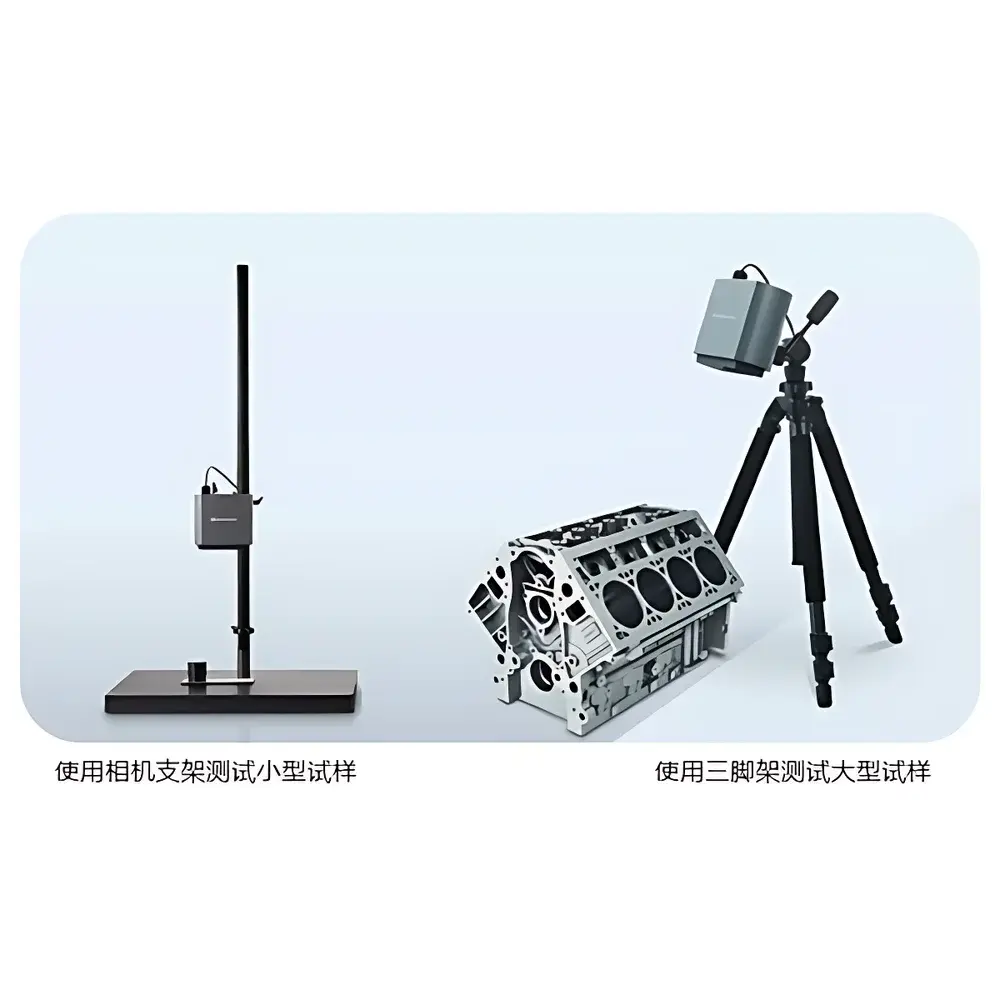
Can the MIV-X inspect curved or rough surfaces?
Yes—within limits of optical focus depth and transducer coupling stability; optional zoom lenses and adjustable standoffs support moderate curvature (radius ≥ 25 mm) and Ra ≤ 3.2 µm finishes.
Is calibration required before each use?
No routine recalibration is needed; however, daily verification using a certified reference sample with known artificial disbonds is recommended per ISO/IEC 17025-aligned lab practice.
What file formats are supported for report generation?
PDF reports with annotated video thumbnails, TIFF image sequences, and CSV displacement time-series data—exportable to LIMS or ELN platforms via standard API hooks.
Does the system meet any international NDT standards?
Its operational methodology supports compliance with ISO 16840 Annex B (non-contact UT methods) and ASTM E2700 Section 6.2 (acoustic emission correlation), though final acceptance depends on site-specific procedure qualification.


