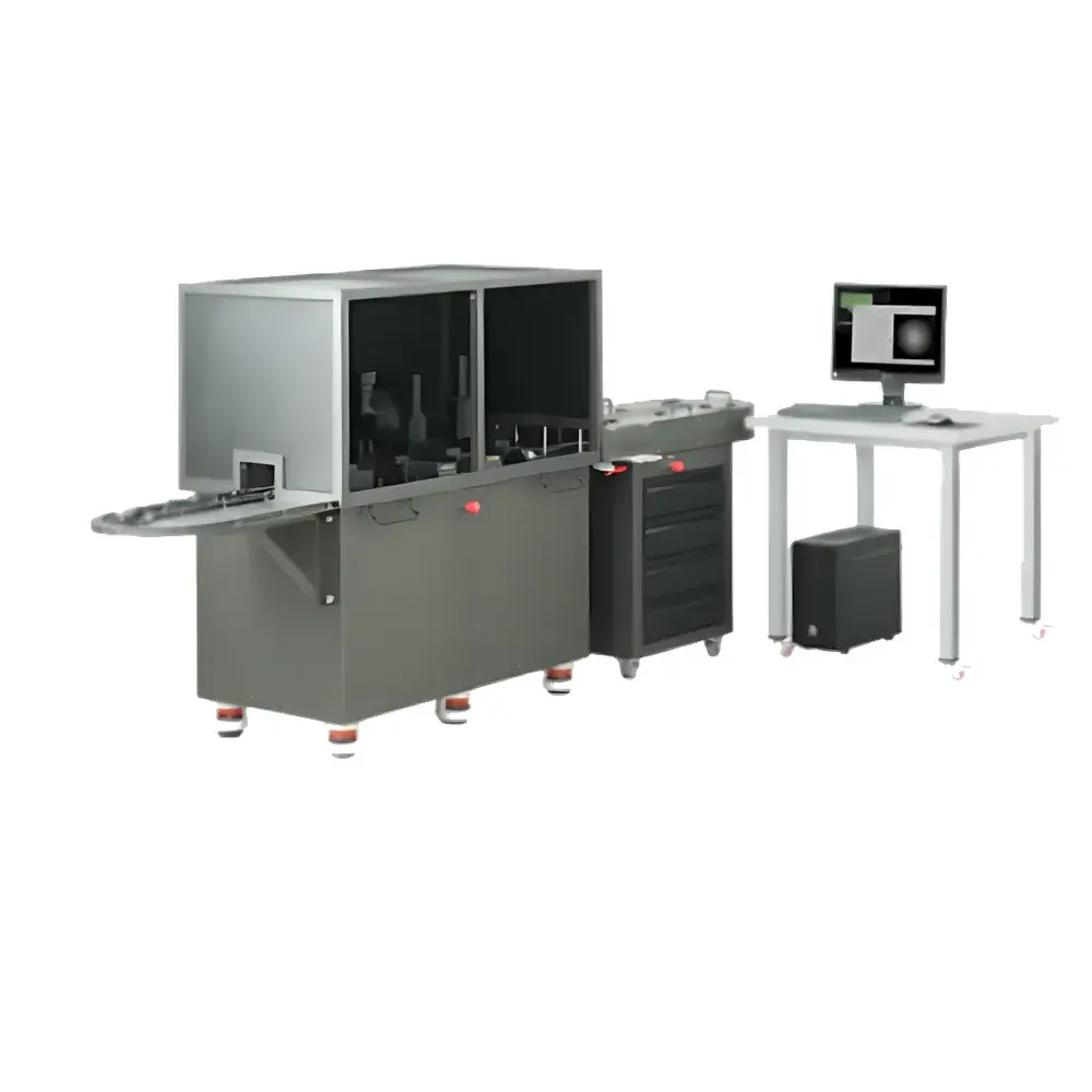
Inframet IMAG Automated Image Intensifier Tube Testing System
| Brand | Inframet |
|---|---|
| Origin | Poland |
| Model | IMAG |
| Configuration Options | IMAG-A, IMAG-A+, IMAG-B |
| Key Measured Parameters | SNR (10–35 @ 0.108 mlx, ±8%), Resolution (4–120 lp/mm, ±3%), MTF (0–60 lp/mm, resolution-dependent uncertainty), Halo (0.2–1.5 mm, ±10%), Effective Cathode Diameter (10–25 mm, ±2%), Bright/Dead Spot Detection (75–500 µm, ±8–12%), Gain (1,000–100,000, ±8%), EBI (0.02–2 lx, ±10%), Max Output Brightness (0.3–20 cd/m², ±4%), Tube Current Consumption (1–100 mA, ±1% or ±0.3 mA), Photocathode Spectral Sensitivity (200–2000 µA/lm, ±7%), Radiant Sensitivity (10–100 mA/W, ±7%) |
| Light Sources | Dual-mode — calibrated 2856 K halogen lamp (photometric measurements) and monochromatic LED (imaging parameter evaluation) |
| Throughput | IMAG-A: 12 tubes/hour (full 17-parameter test in ≤25 min/tube) |
| IMAG-B | 8 tubes/hour (bare + packaged) |
| IMAG-A+ | manual bare-tube photocathode testing (~45 min/tube) |
| Compliance | ISO/IEC 17025-compatible reporting |
| Safety & Integration | Integrated HV power supply (HVP142C for IMAG-B), custom adapter support for non-standard bare-tube geometries and pinouts |
Overview
The Inframet IMAG Automated Image Intensifier Tube (IIT) Testing System is an industrial-grade metrology platform engineered for high-throughput, repeatable characterization of image intensifier tubes across all generations (Gen II, II+, III, III+, IV) and standard phosphor types (P20, P43, P45). Unlike legacy manual or semi-automated systems—such as Inframet’s own ITIP platform—the IMAG system implements full end-to-end automation based on a modular, synchronized four-station architecture. Each station (IMAG1–IMAG4) is purpose-built to execute a discrete subset of IIT performance metrics using calibrated optical projection, high-dynamic-range imaging, and precision photometry. The system operates under rigorously controlled illumination conditions: photometric parameters (e.g., brightness gain, EBI, MOB) are measured using a traceable 2856 K halogen source compliant with MIL-STD-3009 and IEC 61966-2-1 spectral reference requirements, while imaging parameters (MTF, resolution, halo, alignment) employ a stabilized monochromatic LED source optimized for signal-to-noise ratio and spatial fidelity. This dual-source strategy eliminates the spectral mismatch errors inherent in single-LED-only systems when evaluating heterogeneous IIT technologies.
Key Features
- Four-station parallelized architecture enabling concurrent measurement of distinct parameter groups without operator intervention
- Automated tube handling subsystem with magazine-based loading/unloading—operators insert only pre-mounted tubes; no manual repositioning during test sequences
- Comprehensive 17-parameter validation suite covering photometric, geometric, noise, and functional characteristics per ISO 16508 and MIL-STD-3009 Annex C
- Resolution capability up to 120 line pairs per millimeter (lp/mm), validated against NIST-traceable USAF 1951 target standards
- Measurement uncertainty reduced to ≤7% for SNR and ≤3% for resolution repeatability—achievable through fixed-focus optics, thermal-stabilized detectors, and closed-loop illumination feedback
- Dual-mode illumination: 2856 K halogen lamp (photometry) and narrowband LED (imaging), eliminating spectral calibration drift across tube generations
- On-site recalibration support via CALIN calibration kit—no factory return required; recommended interval: 24 months
- Configurable variants: IMAG-A (packaged tubes only), IMAG-A+ (packaged + manual bare-tube photocathode testing), IMAG-B (fully automated bare + packaged tube testing with HVP142C HV supply and custom adapter interface)
Sample Compatibility & Compliance
The IMAG system supports standardized packaged IITs with photocathode diameters of 16 mm, 18 mm, and 25 mm, and accommodates all common phosphor screens (P20, P43, P45). For bare-tube testing (IMAG-B and IMAG-A+ configurations), mechanical and electrical interface specifications must be provided by the customer—including dimensional drawings, pinout schematics, and voltage/current requirements—to enable design and integration of application-specific adapters (up to two unique adapter sets per system). All measurement data outputs conform to ISO/IEC 17025 documentation requirements, including audit trails, instrument calibration status, environmental condition logging (ambient temperature, humidity), and raw image metadata. The system architecture supports FDA 21 CFR Part 11-compliant electronic signatures and role-based access control when deployed in regulated manufacturing environments operating under GLP or GMP frameworks.
Software & Data Management
The IMAG Control Suite is a Windows-based application built on a deterministic real-time kernel, ensuring sub-millisecond synchronization between illumination triggers, image acquisition, HV ramping, and data logging. Test protocols are fully scriptable and parameterizable—users define pass/fail thresholds, sequence order, and conditional branching (e.g., skip MTF if resolution fails initial screening). All measurement results are stored in structured HDF5 files containing embedded calibration coefficients, raw sensor frames, processed MTF curves, SNR histograms, and spot analysis heatmaps. Export options include PDF reports compliant with ISO/IEC 17025 clause 7.8.2, CSV for SPC integration, and XML for MES/ERP ingestion. Audit logs record every user action, configuration change, and calibration event with timestamp, operator ID, and digital signature—enabling full traceability for internal audits or regulatory inspections.
Applications
The IMAG system is deployed in high-volume production lines for defense contractors, OEM night vision device manufacturers, and Tier-1 IIT suppliers where statistical process control (SPC) and lot-level certification are mandatory. It enables continuous monitoring of critical parameters—including gain uniformity, halo magnitude, cathode-MCP spacing, and EBI drift—across production shifts. Its automation reduces dependence on highly trained metrologists, making it suitable for facilities with constrained technical staffing. Research laboratories utilize IMAG-B for comparative benchmarking of next-generation GaAs photocathodes and microchannel plate (MCP) architectures, leveraging its ability to isolate and quantify individual noise contributions (multi-modal, multi-boundary, fixed-pattern). The system also serves as a reference platform for validating accelerated life testing (ALT) protocols, where repeated IMAG measurements over thermal cycling or voltage stress provide quantitative degradation metrics aligned with MIL-STD-810 and MIL-STD-750 methodologies.
FAQ
What is the minimum operator training required to run IMAG-A?
Operators require ≤2 hours of instruction focused solely on tube loading/unloading procedures and basic software navigation. No metrology expertise or optical alignment skills are needed.
Can IMAG test Gen IV filmless IITs?
Yes—provided the tube fits within standard mechanical envelopes and uses compatible phosphors. The system does not assume film presence; all measurements are geometry- and signal-based.
How is calibration traceability maintained?
Primary standards (luminance, resolution, spectral irradiance) are traceable to PTB (Physikalisch-Technische Bundesanstalt) and NIST via Inframet’s accredited calibration laboratory. CALIN kits contain certified reference targets and photodiode standards with documented uncertainty budgets.
Is remote diagnostics supported?
Yes—via encrypted TLS-secured VNC tunnel with session logging. Inframet engineers can monitor system health, review error logs, and validate calibration status without physical access.
What safety certifications does IMAG hold?
CE marking per EN 61010-1:2019 (measurement/control lab equipment), UL 61010-1, and compliance with IEC 62368-1 for HV subsystems (HVP142C). Interlocked HV enclosures prevent exposure during operation.