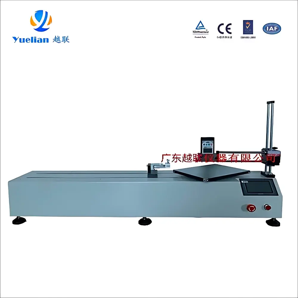
YL-H03C-SV Electrostatic Delamination Voltage Tester
| Brand | Yuelian |
|---|---|
| Origin | Guangdong, China |
| Model | YL-H03C-SV |
| Display Type | Backlit LCD |
| Measurement Principle | Oscillating Electrometer (Electrostatic Induction) |
| Voltage Range (Standard Mode) | 10 V – 19.99 kV |
| Voltage Range (IB Mode) | 1 V – 1999 V |
| Resolution | 1 V (IB Mode), 10 V (Standard Mode) |
| Measurement Distance | 30 mm (fixed focal point via red LED alignment) |
| Sampling Rate | 2 Hz (0.5 s update interval) |
| Test Angle | 180° peel configuration |
| Peel Speed Control | 100–10,000 mm/min (adjustable via 5-inch touch interface) |
| Effective Travel | 500 mm |
| Specimen Width | 50 mm |
| Drive System | Delta servo motor + Delta servo driver |
| Transmission | Precision ball screw + linear guide rails |
| Power Supply | AC 220 V, 50 Hz |
| Rated Power | 400 W |
| Operating Temperature | 0–40 °C |
| Dimensions (Tester Unit) | 68 × 22 × 138 mm (W×D×H) |
| Weight (Unit) | 230 g (incl. battery) |
| Dimensions (Main Frame) | 1363 × 420 × 850 mm (W×D×H) |
| Safety Features | Upper/lower voltage limits, specimen break detection, emergency stop logic |
| Compliance Notes | Designed for laboratory and production-line electrostatic process validation |
Overview
The YL-H03C-SV Electrostatic Delamination Voltage Tester is an engineered instrument for quantifying transient electrostatic potentials generated during the controlled 180° peeling of protective films—commonly used in display manufacturing, semiconductor packaging, and precision optics assembly. It operates on the principle of oscillating electrometer-based electrostatic induction, where a modulated sensing electrode detects charge displacement without physical contact, minimizing perturbation to the measurement field. Unlike passive voltmeters or static field meters, this system captures dynamic voltage profiles across variable peel speeds (100–10,000 mm/min), enabling correlation between mechanical separation kinetics and triboelectric charge generation. Its fixed 30 mm measurement distance—verified optically via integrated red LED focus targeting—ensures repeatability across operator skill levels and environmental conditions within 0–40 °C. The device is not a general-purpose electrostatic monitor but a purpose-built tool for QC/QA labs validating film adhesion stability, ionizer balance efficacy, and ESD-sensitive process windows.
Key Features
- Integrated 5-inch capacitive touchscreen interface with intuitive navigation for speed, mode, and polarity selection—eliminating external PC dependency for routine testing.
- Dual-range voltage measurement: Standard mode (10 V–19.99 kV) for high-energy delamination events; IB (Ion Balance) mode (1 V–1999 V) optimized for low-voltage ionizer verification and fine-balance diagnostics.
- Oscillating-sensor architecture with active compensation for ambient electromagnetic interference—critical when operating near CNC equipment, plasma cleaners, or RF sources.
- Real-time polarity indication (+/−) via dedicated MODE button toggling, essential for distinguishing charge polarity in asymmetric film-substrate systems (e.g., PET/ITO vs. silicon nitride).
- Robust mechanical design: Delta servo-driven motion control ensures precise peel velocity linearity; ball screw and linear guide rails maintain positional accuracy over 500 mm effective travel.
- Self-contained unit operation: Powered by DC 9 V alkaline battery (field-portable) or AC 220 V supply (lab-integrated), with battery-level indicator on backlit LCD.
Sample Compatibility & Compliance
The YL-H03C-SV accommodates standard 50 mm wide protective films—including PET, PE, PU, and silicone-coated variants—mounted on rigid substrates (glass, silicon wafers, or FR-4 PCBs). Its 180° peel geometry conforms to ASTM D903 and ISO 8510-2 methodologies for adhesive release force characterization, though voltage output is reported independently of force data. While not certified to IEC 61340-5-1 or ANSI/ESD S20.20 as a standalone ESD control device, it provides traceable voltage readings required for internal ESD program audits. Data logging supports basic GLP traceability: timestamps, operator ID fields (via touchscreen input), and manual annotation fields are configurable in report exports. No FDA 21 CFR Part 11 compliance is claimed; however, audit trails can be exported as CSV for third-party LIMS integration.
Software & Data Management
The embedded firmware enables on-device storage of up to 200 test records, each containing peak voltage, average voltage, polarity, peel speed, timestamp, and operator tag. Export is performed via USB 2.0 port to FAT32-formatted drives; no proprietary software installation is required. Raw data files include ASCII-encoded columns: “Test_ID, Timestamp_UTC, Mode, Polarity, Max_Voltage_V, Avg_Voltage_V, Peel_Speed_mm_min, Operator_ID”. Optional Python-based parsing scripts (provided in documentation) allow batch statistical analysis—Cp/Cpk calculation, trend charting, and outlier flagging per ISO 22514-2. All firmware updates are delivered as signed .bin files with SHA-256 checksum verification.
Applications
- Qualification of anti-static release liners in OLED module fabrication lines.
- Validation of ionizer decay time and offset voltage per IEC 61340-4-1 Annex B protocols.
- Root-cause analysis of micro-scratches or particle attraction during film lamination steps.
- Comparative evaluation of surface energy modification (e.g., corona treatment, plasma activation) on delamination voltage profiles.
- Process FMEA support: correlating peel voltage spikes (>5 kV) with downstream defect rates in cleanroom assembly.
- Supplier qualification: enforcing maximum allowable delamination voltage thresholds (e.g., ≤1.2 kV at 500 mm/min) in incoming material specifications.
FAQ
Is the YL-H03C-SV suitable for measuring static voltage on non-peeling surfaces?
No. Its sensor and firmware are calibrated exclusively for dynamic voltage acquisition during 180° mechanical delamination. Static field mapping requires a dedicated electrostatic voltmeter (e.g., Trek Model 370).
Why is the oscillating-sensor design sensitive to mechanical shock?
The oscillating electrode relies on micron-level capacitive gap stability; impact-induced misalignment degrades signal-to-noise ratio and introduces zero-drift. Units must be handled per IEC 60068-2-27 for shock resistance.
Can test data be exported directly to Excel or LIMS?
Yes. CSV exports are natively compatible with Microsoft Excel, JMP, and most LIMS platforms supporting ASCII ingestion. No drivers or middleware are needed.
What maintenance is required for long-term calibration stability?
Annual verification using NIST-traceable electrostatic calibrators (e.g., Monroe Model 262A) is recommended. The internal reference capacitor does not drift under normal use but requires re-zeroing after battery replacement.
Does the instrument meet CE or UKCA marking requirements?
It complies with EMC Directive 2014/30/EU (tested to EN 61326-1) and Low Voltage Directive 2014/35/EU. CE marking is applied; UKCA is not currently held but technically achievable upon request.


