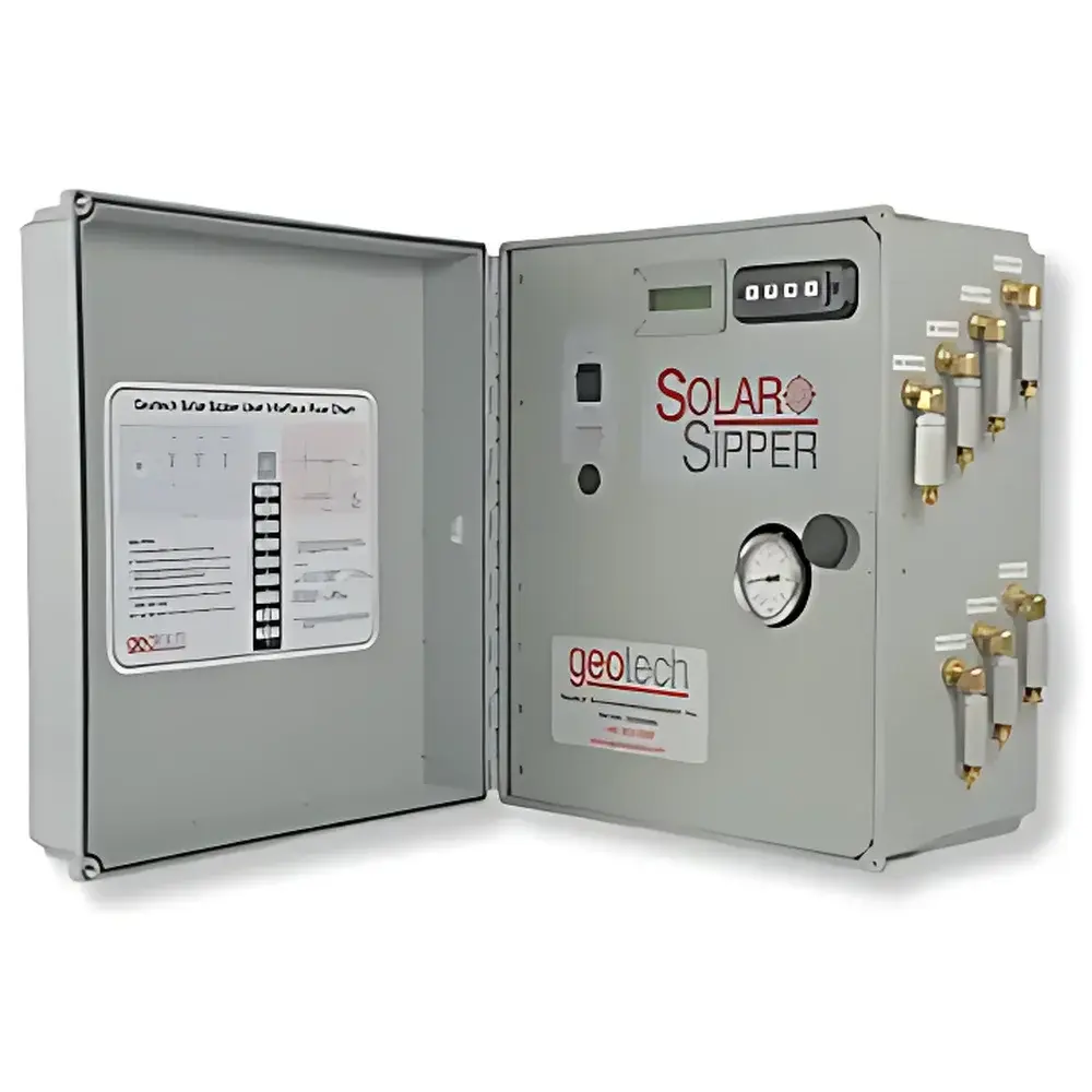
Geotech Sipper Multi-Well Hydrocarbon Recovery System
| Brand | Geotech |
|---|---|
| Model | Sipper |
| Manufacturer | SAIL HERO (Xianhe Environmental Protection) |
| Origin | Hebei, China |
| Manufacturer Type | OEM Producer |
| Power Options | 110–220 V AC single-phase or solar-powered |
| Deployment Capacity | Up to 7 wells |
| Pumping Principle | Pneumatic vacuum-pressure cycling |
| Oil-Water Separation Mechanism | Oleophilic/hydrophobic coalescing membrane skimmer |
| System Architecture | Subsurface pneumatic lift pump + surface collection manifold |
| Compliance Context | Designed for integration into ASTM D6870-compliant LNAPL/DNAPL recovery workflows and EPA Region III/IV remediation protocols |
Overview
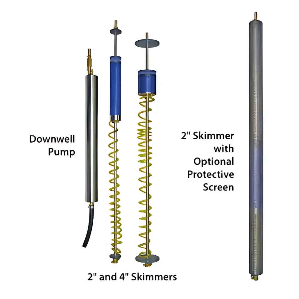
The Geotech Sipper Multi-Well Hydrocarbon Recovery System is an engineered solution for passive and semi-active recovery of light and dense non-aqueous phase liquids (LNAPLs and DNAPLs) from saturated and unsaturated zones across multiple monitoring or extraction wells. It operates on a dual-cycle pneumatic principle—alternating between vacuum-induced drawdown and pressure-assisted discharge—enabling continuous, low-energy hydrocarbon removal without submersible electric motors or mechanical impellers. The system deploys downhole air-lift pumps connected via dedicated riser tubing to a surface-mounted control manifold and oil-water separation skimmer. A proprietary oleophilic/hydrophobic coalescing membrane selectively captures hydrocarbons while rejecting free-phase water, ensuring high-purity recovered product suitable for reclamation or disposal per RCRA Subtitle C guidelines. Its modular architecture supports scalable deployment in heterogeneous geologies, including sandy aquifers, fractured bedrock, and clay-rich transition zones where conventional pump-and-treat systems exhibit low efficiency.
Key Features
- Multi-well coordination capability: Simultaneous operation across up to seven discrete wells using shared compressed air supply and centralized cycle timing control.
- Dual-power flexibility: Fully functional under 110–220 V AC single-phase grid power or off-grid photovoltaic arrays with battery-backed DC-to-AC inverters (compatible with 12/24/48 V nominal solar configurations).
- Subsurface pneumatic lift design: Eliminates electrical components below grade—reducing explosion risk in volatile hydrocarbon environments and enabling Class I, Division 1 zone compliance when properly housed.
- Oleophilic/hydrophobic membrane skimmer: Achieves >95% hydrocarbon capture efficiency from emulsified and free-phase effluent; membrane modules are replaceable and rated for >12 months continuous service under typical LNAPL loadings.
- Compact surface footprint: Control cabinet dimensions ≤ 750 mm × 550 mm × 300 mm (W × D × H); designed for rapid installation on concrete pads, gravel berms, or temporary steel platforms.
- Fail-safe vacuum-pressure sequencing: Microprocessor-controlled solenoid valves ensure precise dwell times for fill (vacuum) and discharge (pressure) phases—minimizing air consumption and maximizing volumetric recovery per cycle.
Sample Compatibility & Compliance
The Sipper system recovers a broad spectrum of petroleum-derived hydrocarbons—including gasoline-range organics (GRO), diesel-range organics (DRO), heating oil No. 2, and chlorinated solvents such as PCE and TCE—when present as discrete-phase NAPLs. It is validated for use in sites governed by U.S. EPA OSWER Directive 9200.4-18P (LNAPL Remediation), ASTM D6870 (Standard Guide for LNAPL Site Characterization), and ISO 15148:2017 (Soil quality — Determination of hydrocarbon content). All wetted materials (EPDM diaphragms, stainless-steel manifolds, fluoropolymer-coated membranes) comply with NSF/ANSI Standard 61 for incidental contact with potable groundwater. System data logging meets GLP audit requirements for field remediation documentation.
Software & Data Management
The integrated Sipper Control Unit includes RS-485 Modbus RTU output and optional cellular telemetry (LTE-M/NB-IoT) for remote cycle monitoring, air pressure trending, and alarm notification (e.g., low vacuum, membrane clogging, power loss). Logged parameters include cumulative cycle count, total recovered volume (calibrated via gravimetric verification), average vacuum depth (kPa), and solar charge state (if applicable). Data exports conform to ASTM E2531-22 structured CSV format and are compatible with common environmental data management platforms (EDMS), including EQuIS, GeoVision, and ArcGIS Field Maps. Audit trails support 21 CFR Part 11-compliant electronic signatures when deployed with validated third-party LIMS integration.
Applications
- Long-term managed aquifer remediation at legacy UST sites (e.g., former gas stations, bulk fuel terminals).
- Source-zone depletion prior to thermal treatment or ISCO injection in DNAPL-impacted fractured rock.
- Interim containment and recovery during tank farm decommissioning or pipeline right-of-way maintenance.
- Emergency response deployment following aboveground storage tank overfills or railcar derailments involving volatile organics.
- Passive plume stabilization in karst terrains where hydraulic gradients limit conventional extraction feasibility.
FAQ
What types of NAPLs can the Sipper system recover?
It is optimized for free-phase and pooled LNAPLs (e.g., gasoline, diesel, jet fuel) and select DNAPLs (e.g., chlorinated ethenes, coal tar fractions) exhibiting sufficient mobility to enter the pump intake under applied vacuum.
Is regulatory approval required before deploying the Sipper system?
Yes—site-specific permitting is mandatory per local environmental authority requirements; however, the system’s design aligns with EPA-approved remedial technologies listed in the CLU-IN Technology Screening Matrix.
Can the system operate unattended for extended periods?
Yes—field deployments exceeding 12 months have been documented with biannual membrane replacement and quarterly calibration checks per manufacturer-recommended maintenance schedule.
Does the system require pretreatment of influent groundwater?
No pretreatment is needed; however, sediment-laden wells should be equipped with downhole sand traps to prevent membrane fouling and extend service intervals.
How is recovered hydrocarbon volume quantified?
Volumetric measurement is performed via calibrated sight-glass accumulation chambers with temperature-compensated density correction; optional load-cell integration enables mass-based reporting per ASTM D129-20.
Related Products