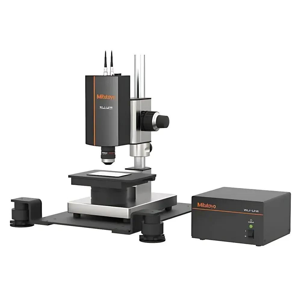
Mitutoyo WLI-Unit Series White Light Interferometric Microscope with WLI Plan Apo Objectives
| Brand | Mitutoyo |
|---|---|
| Model | WLI-Unit-003 / WLI-Unit-005 / WLI-Unit-010 |
| Sensor Head Cable Length | 5 m |
| Compatible Objectives | WLI Plan Apo Series |
| Imaging Magnification | 1× |
| Focal Length (f) | 100 mm |
| Scanner Dimensions / Mass | 108 × 68 × 191 mm / 1.7 kg |
| Z-Axis Measurement Range | 8000 µm |
| WLI Measurement Z-Range (High-Throughput Mode) | 2100 µm / 1900 µm / 1700 µm |
| Acquisition Time @ 20 µm Range | 3 s / 4 s / 6 s |
| Z-Axis Resolution | ≤ 4 nm |
| Z-Axis Repeatability | ≤ 40 nm |
| Software | WLIPAK |
| Calibration Tools | Pixel Calibration SW, MCubeMap Analysis Module |
| Image Acquisition | Matrox Frame Grabber (included) |
| SDK | WLI-Unit Control Library with Example Code and GUI Templates |
Overview
The Mitutoyo WLI-Unit Series is a precision white light interferometric (WLI) microscope system engineered for non-contact, high-resolution 3D surface topography and micro-roughness characterization. Based on the principle of low-coherence interferometry, the system generates interference fringes by splitting broadband white light between a reference arm and a measurement arm—where the sample surface acts as the reflective element. Unlike laser-based interferometers, WLI eliminates coherence noise and enables robust phase retrieval across surfaces with heterogeneous reflectivity, including mixed metallic-dielectric or polished-etched regions. The WLI-Unit integrates seamlessly with Mitutoyo’s proprietary WLI Plan Apo objectives—designed specifically to preserve fringe contrast over wide reflectivity ranges (0.1%–100%) without manual gain adjustment. This architecture ensures quantitative height data acquisition under consistent illumination conditions, even when high- and low-reflectance features coexist within a single field of view—a critical capability for semiconductor metrology, MEMS inspection, and precision mold validation.
Key Features
- Non-contact 3D surface profiling with sub-nanometer Z-axis resolution (≤ 4 nm) and ≤ 40 nm repeatability across full measurement range
- Simultaneous high-fidelity measurement of surfaces with disparate reflectivity—no dynamic exposure compensation required
- Z-scanning via integrated objective-mounted piezo actuator with 8000 µm total travel and programmable scan modes (high-throughput, standard, high-resolution)
- WLI Plan Apo objectives featuring long working distance (60 mm parfocal distance), high numerical aperture (NA), flat-field correction, and apochromatic design for minimal chromatic aberration
- Integrated beam splitter and reference mirror housed within each objective—eliminating external alignment sensitivity and enhancing vibration immunity
- Compact sensor head (108 × 68 × 191 mm; 1.7 kg) compatible with standard optical tables, coordinate measuring machines (CMMs), and automated inspection platforms
Sample Compatibility & Compliance
The WLI-Unit supports measurement of optically reflective and semi-reflective samples—including silicon wafers, sapphire substrates, hardened steel tooling, optical coatings, and polymer-molded microstructures. Its insensitivity to surface reflectivity gradients meets ASTM E2922–22 requirements for 3D surface texture analysis in manufacturing quality control. System calibration traceability aligns with ISO/IEC 17025-accredited procedures using NIST-traceable step-height standards. The hardware and WLIPAK software support audit-ready data logging compliant with FDA 21 CFR Part 11 when configured with electronic signatures and secure user access controls. All mechanical and optical components adhere to RoHS 2011/65/EU directives and CE marking requirements for laboratory instrumentation.
Software & Data Management
WLIPAK is a dedicated, Windows-based application providing real-time fringe analysis, surface reconstruction, and ISO 25178-compliant roughness parameter extraction (Sa, Sq, Sz, Sdr, etc.). The software includes pixel-level calibration routines, tilt correction algorithms, and automatic defect segmentation tools. For integration into automated production lines or custom metrology workflows, the WLI-Unit SDK delivers a C/C++ and Python-compatible control library with documented APIs, thread-safe command queues, and GUI-ready example code—including a fully functional Qt-based reference interface. Optional MCubeMap analysis module extends capabilities to curvature mapping, slope distribution histograms, and layer-thickness estimation on transparent films. Raw interferogram data (16-bit TIFF stacks) and processed height maps are stored in vendor-neutral formats supporting third-party post-processing in MATLAB, Python (OpenCV, scikit-image), or Metrology Suite environments.
Applications
- Semiconductor process control: trench depth, contact hole profile, CMP uniformity, and lithographic resist topography
- Precision machining validation: surface finish of injection molds, turbine blades, and medical implant surfaces
- MEMS and micro-optics: actuator displacement, mirror flatness, grating pitch verification, and lenslet array form error
- Advanced materials R&D: graphene layer thickness mapping, thin-film stress-induced buckling, and corrosion pit morphology quantification
- Calibration laboratory use: certification of step-height artifacts, roughness standards, and stylus profiler reference samples
FAQ
What is the maximum measurable surface slope angle with the WLI Plan Apo 1× objective?
The system maintains reliable fringe contrast up to ±15° local surface inclination under standard illumination—beyond which optional tilting stages or multi-angle stitching protocols are recommended.
Can the WLI-Unit be synchronized with external motion controllers or trigger signals?
Yes—via TTL-compatible trigger I/O ports and Ethernet-based command interface, enabling precise coordination with motorized XY stages, environmental chambers, or inline production sensors.
Is GLP/GMP-compliant data archiving supported out-of-the-box?
WLIPAK supports configurable audit trails, electronic signatures, and encrypted database logging; full 21 CFR Part 11 compliance requires deployment on validated IT infrastructure and documented SOPs.
Does the system require periodic recalibration of the Z-axis encoder?
No—the piezo-driven Z-scanner uses closed-loop capacitance feedback; only annual verification against traceable step-height standards is recommended per ISO 10360-5.
Are there compatibility constraints with third-party image acquisition hardware?
While Matrox frame grabbers are supplied and fully tested, the SDK exposes low-level camera control registers—enabling integration with select PCIe Gen3 vision cards meeting GenICam v3.1 specifications.