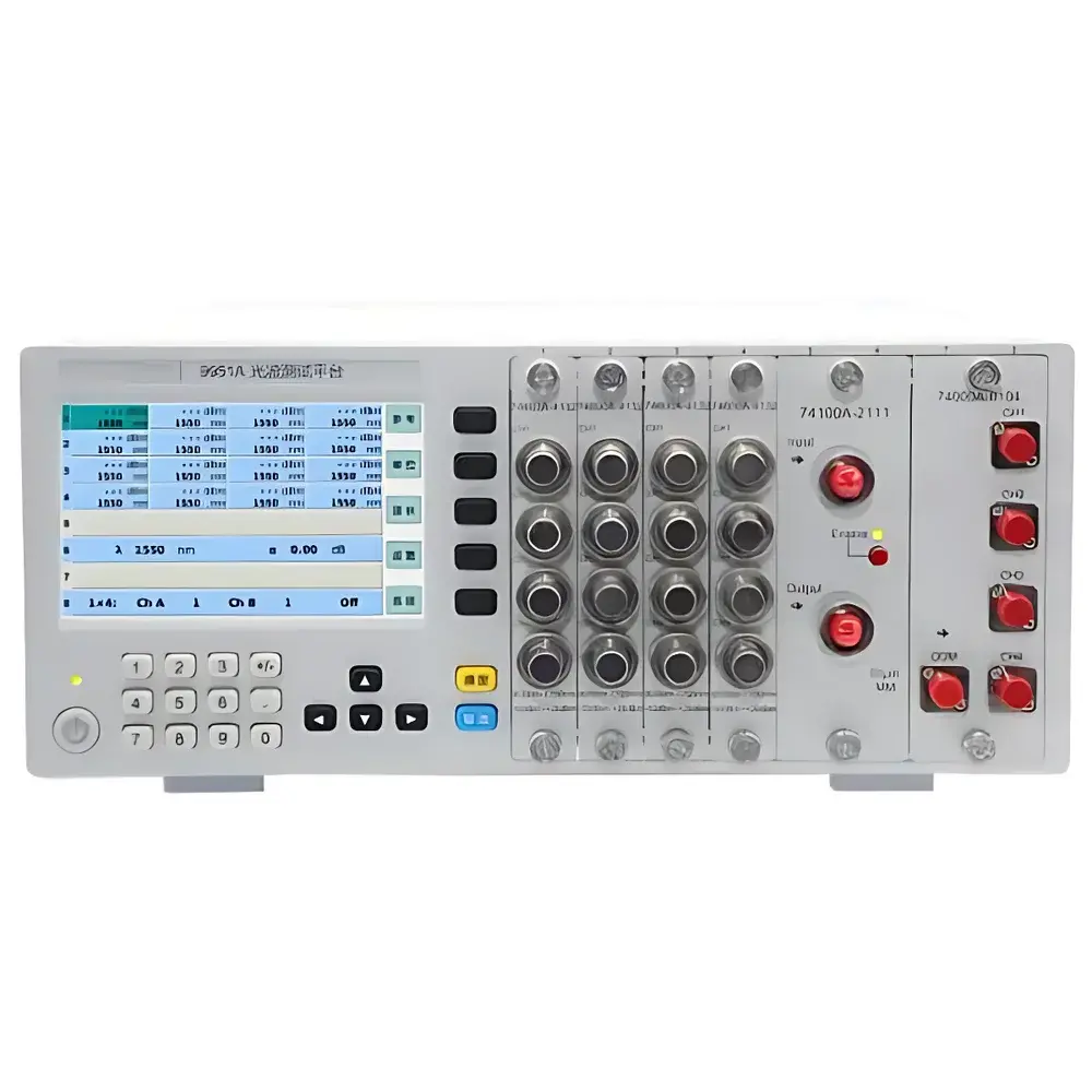
Auniontech 9951A/9951Y Modular Multi-Channel Optical Waveform Test Platform
| Brand | Auniontech |
|---|---|
| Origin | Shanghai, China |
| Model | 9951A (8-slot) / 9951Y (18-slot) |
| Interface Support | LAN (64 concurrent clients), RS232C (9951A only), USB |
| Power Meter Range | –80 dBm to +26 dBm |
| Wavelength Range | 800–1700 nm |
| Attenuation Range | 0–65 dB |
| Polarization Scrambling | ≤5% DOP after scrambling |
| Display | 4.3″ HD touchscreen (9951A only) |
| Module Auto-ID | Yes |
| Compliance | CE-marked |
Overview
The Auniontech 9951A and 9951Y Modular Multi-Channel Optical Waveform Test Platforms are engineered for high-throughput, reconfigurable photonic test environments in R&D laboratories and manufacturing facilities. Built on a scalable chassis architecture, these platforms operate on the principle of modular instrumentation—where standardized optical measurement and control functions (e.g., power detection, attenuation, switching, polarization manipulation) are implemented as hot-swappable, auto-identified modules. Each platform supports precise, traceable optical signal characterization across the full telecom and datacom wavelength band (800–1700 nm), enabling end-to-end validation of passive and active photonic components under controlled, repeatable conditions. The system’s deterministic timing, low insertion loss module interconnects, and synchronized multi-channel acquisition capability make it suitable for applications requiring statistical process control (SPC), batch calibration, and automated pass/fail decision logic in GLP- and GMP-aligned workflows.
Key Features
- Modular chassis with 8 (9951A) or 18 (9951Y) universal module slots—supports mixed-function configurations without hardware modification
- Auto-detection and firmware negotiation upon module insertion—eliminates manual configuration and reduces setup errors
- Integrated LAN interface compliant with TCP/IP and UDP protocols; supports up to 64 concurrent remote clients for distributed test orchestration
- Full-wavelength calibrated optical power meters (–80 dBm to +26 dBm dynamic range) with NIST-traceable calibration options available
- Single-mode and multimode optical attenuators with 0.01 dB resolution and <±0.2 dB linearity across 0–65 dB range
- Low-crosstalk optical switches (1×N, 2×N, M×N configurations) with sub-millisecond switching time and <0.5 dB insertion loss
- Polarization scramblers based on dual-liquid-crystal or electro-optic modulation—achieving ≤5% degree of polarization (DOP) over Poincaré sphere coverage
- 4.3″ capacitive touchscreen GUI on 9951A model—enabling local operation, real-time waveform visualization, and quick parameter adjustment
- Standard SCPI-compatible command set for remote control via Ethernet, RS232C (9951A only), or USB virtual COM port
Sample Compatibility & Compliance
The platform accommodates standard fiber-optic interfaces including FC/PC, SC/PC, LC/PC, and angled physical contact (APC) connectors across all modules. It is designed for use with single-mode (SMF-28, G.652.D), multimode (OM3/OM4), and polarization-maintaining (PM) fibers. All optical modules comply with IEC 61300-3-35 for mechanical and environmental robustness during repeated mating cycles. Electrical safety conforms to IEC 61010-1; electromagnetic compatibility meets EN 61326-1 (industrial environment). Optional factory calibration certificates include uncertainty budgets traceable to national metrology institutes (e.g., NIM China). The system architecture supports audit-ready operation under ISO/IEC 17025 and FDA 21 CFR Part 11 when paired with validated software environments.
Software & Data Management
Auniontech provides the optional AunionSoft Control Suite—a Windows-based application supporting script-driven automation (Python, LabVIEW, MATLAB APIs), real-time data logging, and CSV/Excel export with timestamping and channel metadata. Raw measurements include wavelength-stamped power values, attenuation settings, switch state logs, and scrambler duty-cycle records. Audit trail functionality captures user login events, parameter changes, and module swap history—essential for regulatory review. For integration into MES or factory automation systems, the platform exposes RESTful API endpoints and Modbus TCP registers for status polling and command dispatch. All communication layers implement TLS 1.2 encryption where supported by host infrastructure.
Applications
- Characterization of passive components: insertion loss, return loss, PDL, and wavelength-dependent response of isolators, couplers, WDM filters, and FBGs
- Active device testing: LIV (light-current-voltage) curve acquisition, TEC control verification, and modulation depth analysis for DFB/EML lasers and SOAs
- Transceiver module production: parallel burn-in testing, eye diagram pre-screening, and channel uniformity validation across QSFP-DD, OSFP, and COBO form factors
- Photonic integrated circuit (PIC) probe station integration: wafer-level testing of SiPh and InP-based circuits using multi-port optical routing and synchronized power monitoring
- Research-grade polarization-sensitive experiments: Mueller matrix acquisition, depolarization quantification, and coherence length mapping in interferometric setups
FAQ
What is the maximum number of modules that can be installed simultaneously?
The 9951A supports up to 8 modules; the 9951Y supports up to 18 modules. Slot allocation is fixed per chassis—no expansion beyond native capacity.
Can modules from different generations be used interchangeably?
Only modules bearing the “995x Series” designation and firmware revision ≥v2.1 are guaranteed compatible. Legacy modules require firmware update or adapter firmware emulation.
Is optical power meter calibration included with purchase?
Factory calibration at three wavelengths (1310 nm, 1490 nm, 1550 nm) is standard. Full-band (800–1700 nm) NIST-traceable calibration is available as an optional add-on with certificate.
Does the platform support synchronization with external instruments such as oscilloscopes or bit error rate testers?
Yes—via TTL trigger input/output ports on the rear panel and programmable delay settings in the SCPI command set. Synchronization jitter is <100 ns RMS.
How is firmware updated?
Firmware updates are performed over LAN or USB using signed binary packages delivered through Auniontech’s secure customer portal. Updates preserve user configuration and calibration data.