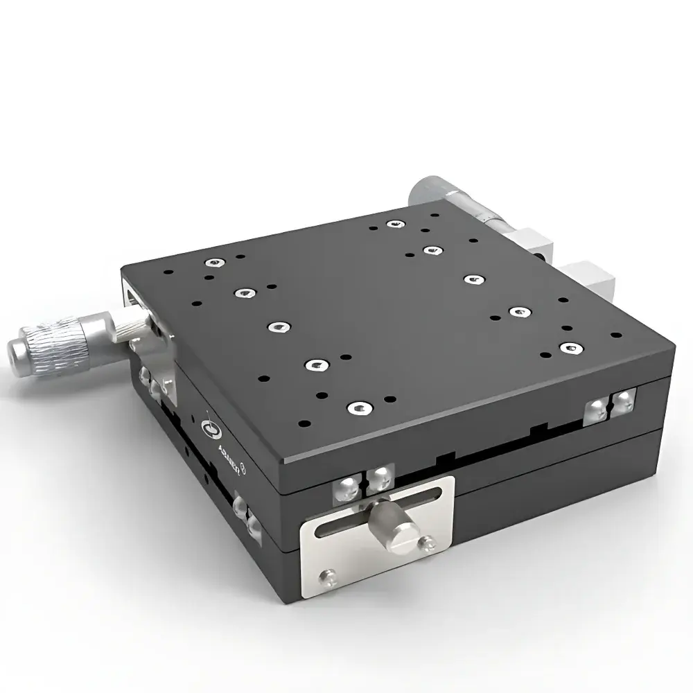
Abner 125×125 mm Manual XY Translation Stage
| Brand | Abner |
|---|---|
| Travel Range (X/Y) | 12.5 mm each axis |
| Drive Mechanism | Micrometer-Driven with Differential Screws |
| Repeatability | ≤ ±1 µm |
| Guide System | Crossed-Roller Bearings |
| Base Material | Anodized Aluminum Alloy (6061-T6) |
| Mounting Pattern | Standard M4/M6 Threaded Holes on 25 mm Grid |
| Locking Mechanism | Dual Knob-Actuated Mechanical Clamp |
| Compliance | ISO 9001 Certified Manufacturing |
| Origin | Jiangsu, China |
| Product Type | Manual Precision Translation Stage |
Overview
The Abner 125×125 mm Manual XY Translation Stage is a high-stability, two-axis orthogonal positioning platform engineered for precision optical alignment and micro-positioning tasks in research laboratories and industrial metrology environments. Based on the proven principle of orthogonal linear motion transmission via crossed-roller bearing guideways, this stage delivers deterministic, low-hysteresis displacement along both X and Y axes—each with a nominal travel range of 12.5 mm. Its mechanical architecture eliminates backlash and elastic deformation commonly observed in lead-screw or flexure-based systems, ensuring consistent kinematic behavior under static and dynamic loading conditions. Designed for integration into optical benches, laser cavities, interferometric setups, and semiconductor inspection stations, the stage operates without external power, making it suitable for EMI-sensitive or vacuum-compatible configurations when specified with non-magnetic hardware.
Key Features
- Crossed-Roller Bearing Guidance: High-rigidity, low-friction linear motion system with preloaded rollers ensures minimal wobble (< 5 µrad tilt error) and axial runout (< 0.5 µm), critical for beam path stability in collimation and focus alignment.
- Micrometer-Driven Adjustment: Dual 10-µm resolution micrometer heads (0–12.5 mm range) with vernier scales enable repeatable manual positioning; calibrated against NIST-traceable standards per batch.
- Anodized Aluminum Construction: 6061-T6 aluminum body with hard-anodized (Type III) surface finish (≥ 50 HV hardness) provides enhanced wear resistance, dimensional stability across thermal gradients (CTE: 23.6 × 10⁻⁶ /°C), and compatibility with cleanroom Class 100 protocols.
- Integrated Mechanical Locking: Dual independent locking knobs apply uniform clamping force to both axes simultaneously, suppressing drift during vibration-prone operations without inducing frame distortion.
- Modular Mounting Interface: Standardized 25 mm pitch grid of M4 and M6 threaded holes enables direct attachment to optical rails (e.g., Thorlabs TR series), breadboards (e.g., Newport 9118), or custom fixtures using industry-standard fasteners.
Sample Compatibility & Compliance
This translation stage accommodates payloads up to 5 kg with center-of-gravity within ±3 mm of the platform centerline—ensuring optimal load distribution across the bearing raceways. It complies with ISO 9001:2015 manufacturing quality management requirements and meets RoHS Directive 2011/65/EU material restrictions. While not certified to ISO 10110 or MIL-STD-810G out-of-box, its mechanical design adheres to fundamental principles referenced in ISO 10360-2 (coordinate measuring machine performance verification) for linear stage repeatability assessment. For GLP/GMP-regulated applications, documentation packages—including raw material certifications, surface finish test reports, and assembly traceability logs—are available upon request.
Software & Data Management
As a fully manual device, the Abner 125×125 stage does not incorporate embedded electronics, firmware, or digital interfaces. Consequently, no proprietary software, drivers, or data logging functionality is provided. Position tracking must be performed externally using calibrated optical encoders, laser interferometers (e.g., Keysight 5530), or coordinate measuring machines. However, the stage’s standardized mounting geometry and documented dimensional tolerances (±0.02 mm per feature) support seamless integration into automated workflows when paired with third-party motion controllers and vision-guided alignment systems compliant with IEEE 1394 or USB3 Vision standards.
Applications
- Laser beam steering and cavity mirror alignment in DPSS and ultrafast oscillator systems
- Objective lens positioning in confocal and super-resolution microscopy platforms
- Wafer-level alignment during photomask inspection and lithography tool calibration
- Optical component co-alignment in fiber coupling assemblies (e.g., PM fiber pigtailing)
- Calibration reference stage for verifying stage accuracy in multi-axis nanopositioning systems
- Education-grade instrumentation for undergraduate optics labs demonstrating wavefront manipulation and interference geometry
FAQ
What is the maximum recommended payload for this stage?
The stage is rated for static loads up to 5 kg when centered; off-center loading exceeding ±3 mm from the geometric center reduces effective stiffness and may compromise repeatability.
Can this stage be used in vacuum environments?
Standard units are not vacuum-rated due to lubricant outgassing from the micrometer threads and bearing grease; however, vacuum-compatible variants with dry-film lubricants and stainless-steel hardware are available under custom order (minimum batch: 5 units).
Is thermal expansion compensated in the design?
No active compensation is implemented; users must account for aluminum’s coefficient of thermal expansion (23.6 × 10⁻⁶ /°C) in long-term stability calculations—especially in temperature-controlled optical tables where ΔT > ±1°C affects sub-micron alignment fidelity.
Are replacement micrometer heads available separately?
Yes—standard 0–12.5 mm, 10-µm resolution micrometers with M10×0.5 thread are supplied as service parts (P/N: ABN-MICRO-125-10UM); calibration certificates issued per ANSI B89.1.10M-2018.
Does the stage include mounting hardware?
No mounting screws or adapters are included; users must select appropriate M4 or M6 cap screws based on their baseplate thickness and torque requirements (recommended: 1.2–1.5 N·m for M4, 2.5–3.0 N·m for M6).