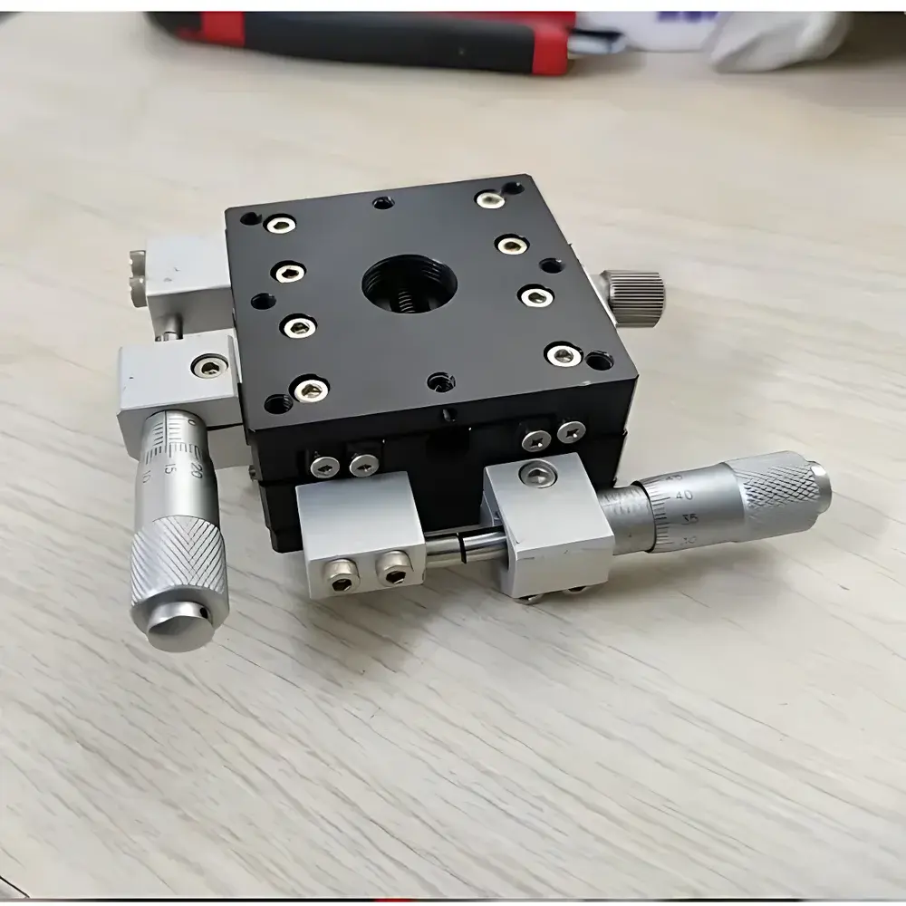
Abner 60×60 mm Manual XY Translation Stage with Crossed-Roller Bearings
| Brand | Abner |
|---|---|
| Origin | Jiangsu, China |
| Model | 60×60 mm Dual-Axis Manual Translation Stage |
| Stage Surface | 60 mm × 60 mm |
| Drive Mechanism | Micrometer Adjusters (0.01 mm resolution) |
| Guiding System | Precision Crossed-Roller Bearings |
| Material | Anodized Aluminum Alloy (6061-T6) |
| Mounting | Standard M3 and M4 Tapped Holes on Base and Top Plate |
| Locking | Dual-Axis Mechanical Locking Screws |
| Product Type | Manual Translation Stage |
| Compliance | Designed for ISO/IEC 17025-aligned lab environments |
Overview
The Abner 60×60 mm Manual XY Translation Stage is a precision-engineered optical positioning platform designed for demanding laboratory and engineering applications requiring sub-millimeter repeatability and mechanical stability. Built upon the fundamental principle of constrained linear motion via orthogonal kinematic coupling, this stage employs a dual-axis orthogonal architecture where independent X- and Y-axis movements are realized through high-fidelity micrometer-driven translation mechanisms guided by preloaded crossed-roller bearings. This configuration eliminates parasitic rotation and minimizes Abbe error—critical for alignment-critical tasks such as laser beam steering, objective lens positioning in microscopy, and sample registration in optical interferometry. The monolithic aluminum alloy body (6061-T6) is CNC-machined to ensure dimensional integrity and thermal homogeneity, while the anodized surface provides consistent coefficient of friction and long-term resistance to oxidation and mild chemical exposure typical in cleanroom and wet-lab settings.
Key Features
- Precision crossed-roller bearing guides on both axes deliver low hysteresis (< 2 µm), high load capacity (up to 5 kg axial static load), and smooth motion with minimal stick-slip behavior—essential for tactile manual adjustment under microscope observation.
- Integrated micrometer adjusters with engraved 0.01 mm graduations and vernier scales enable direct readout of displacement; backlash is mechanically compensated via spring-loaded thimble preload.
- Dual-axis independent locking system uses knurled brass locking screws with positive torque feedback—ensuring positional retention during vibration-prone operations or equipment transport.
- Standardized mounting interface includes a 4×M4 pattern on the top plate (centered on 60 mm square) and a 4×M3 + 4×M4 array on the base, enabling modular integration with Thorlabs-compatible posts, Kinetic Systems breadboards, and custom optomechanical fixtures.
- Anodized surface finish (Type II, 15–20 µm thickness) meets MIL-A-8625F specifications for wear resistance and electrical insulation, supporting ESD-safe handling in semiconductor metrology workflows.
Sample Compatibility & Compliance
This translation stage supports rigid samples up to 60 mm × 60 mm footprint and 5 kg mass, including silicon wafers, glass substrates, fiber optic collimators, and microfluidic chips. It is routinely deployed in environments adhering to ISO 14644-1 Class 5 cleanrooms and conforms to mechanical safety requirements outlined in ISO 12100 for manually actuated laboratory equipment. While not certified to IEC 61000-6-2/3, its passive construction ensures electromagnetic compatibility in mixed-signal optical setups. The design facilitates traceable calibration per ISO/IEC 17025 when used with certified displacement sensors (e.g., capacitive probes or laser interferometers) for uncertainty budgeting in metrology-grade applications.
Software & Data Management
As a fully manual stage, it operates without embedded electronics, firmware, or software dependencies—eliminating cybersecurity concerns and ensuring deterministic behavior across decades of service life. Positional records are maintained externally via lab notebooks, LIMS entries, or digital calibration logs compliant with GLP and FDA 21 CFR Part 11 when paired with electronic measurement tools. Its mechanical simplicity enables seamless incorporation into validated workflows in regulated industries including medical device R&D and pharmaceutical analytical method development.
Applications
- Optical alignment of diode lasers, spatial filters, and interferometric cavities in university teaching labs and industrial photonics R&D.
- Manual coarse/fine positioning of specimens under inverted and confocal microscopes, especially where motorized stages introduce electromagnetic interference or heat drift.
- Stage calibration reference in automated wafer inspection systems—used to verify repeatability of robotic pick-and-place actuators.
- Integration into custom-built optical coherence tomography (OCT) sample arms requiring stable, non-magnetic, and non-outgassing motion platforms.
- Prototyping fixture for micro-assembly jigs in MEMS packaging lines, leveraging standardized mounting holes for rapid reconfiguration.
FAQ
What is the maximum allowable load for this stage?
The stage supports up to 5 kg static load distributed evenly across the 60 mm × 60 mm surface. Dynamic loads exceeding 2 kg at >1 Hz frequency are not recommended due to lack of damping elements.
Can this stage be mounted vertically or upside-down?
Yes—its symmetrical bearing preload and gravity-independent micrometer mechanism allow orientation flexibility; however, vertical use requires external anti-drop hardware for safety-critical applications.
Is the anodized coating electrically insulating?
Yes—the Type II anodization provides surface resistivity >10⁹ Ω·cm², suitable for electro-optic experiments where ground-loop isolation is required.
Are replacement micrometer knobs available separately?
Abner supplies OEM-compatible micrometer assemblies (PN: AB-MICRO-01) with metric M6×0.5 threads and 0.01 mm scale fidelity.
Does this stage meet vacuum compatibility requirements?
It is not UHV-rated; outgassing rates have not been measured per ASTM E595. For medium-vacuum use (<10⁻³ mbar), optional vacuum-bakeable lubricants can be applied to bearing races upon request.