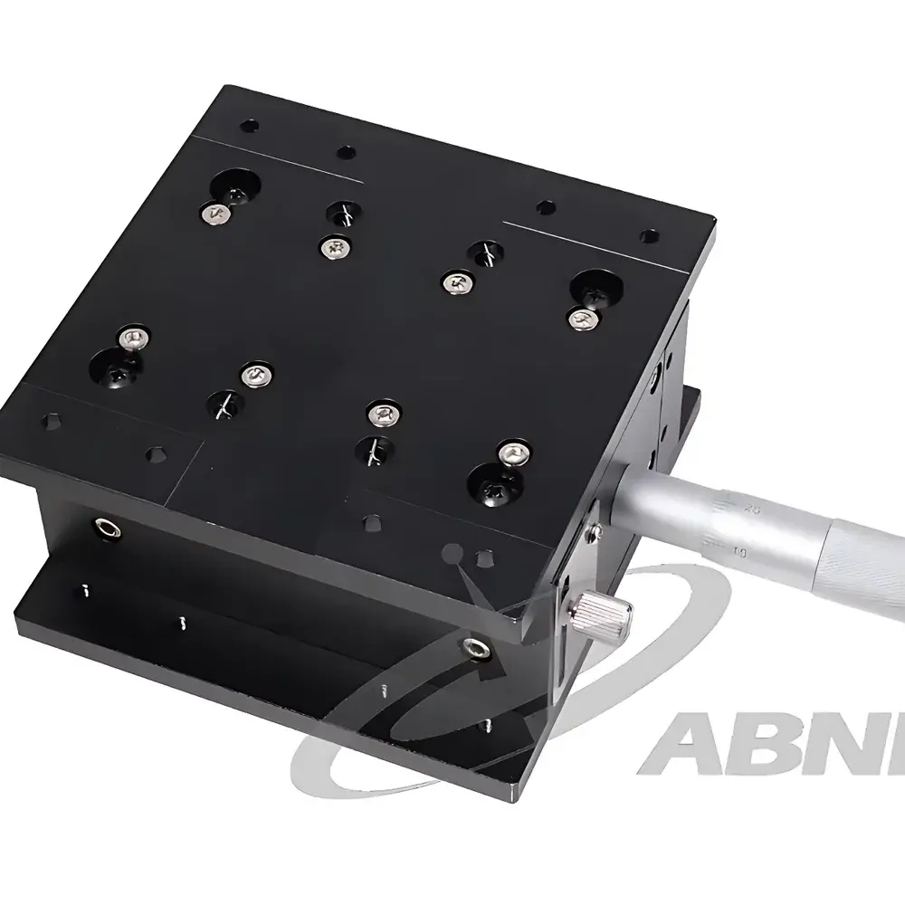
Abner Z-Axis Manual Vertical Translation Stage with Crossed-Roller Bearings and Micrometer Drive
| Brand | Abner |
|---|---|
| Origin | Jiangsu, China |
| Product Type | Manual Translation Stage |
| Model | Z-Series Micrometer-Driven Vertical Stage |
| Construction | CNC-Machined Anodized Aluminum Body |
| Bearing System | Preloaded Crossed-Roller Linear Guides |
| Drive Mechanism | Precision Micrometer Head (0.01 mm Graduation) |
| Load Capacity | ≤ 5 kg (Static, Center-Loaded) |
| Repeatability | ±1 µm |
| Travel Range | 25 mm Standard (Custom Options Available) |
| Mounting Interface | Dual-Side M6 Threaded Hole Pattern (25 mm Grid) |
| Compliance | Designed for ISO/IEC 17025-Compatible Lab Environments |
| Software Integration | Standalone Mechanical Operation (No Electronic Control Required) |
Overview
The Abner Z-Series Manual Vertical Translation Stage is an engineered mechanical positioning solution designed for high-stability, sub-micron repeatable vertical displacement in optical and precision metrology applications. Based on the fundamental principle of constrained linear motion via preloaded crossed-roller bearing assemblies, this stage eliminates rotational play and axial backlash—critical requirements for maintaining collimation integrity in laser alignment, objective focusing in microscopy, and height-sensitive sample interrogation in surface characterization setups. Unlike plain bushing or ball-bearing slides, the crossed-roller configuration provides multi-directional rigidity with near-zero deflection under off-axis loading, ensuring orthogonal motion fidelity across its full 25 mm travel range. The stage’s monolithic aluminum structure—machined from 6061-T6 billet and finished with hard-anodized coating (≥25 µm thickness)—delivers thermal stability (CTE ≈ 23.6 × 10⁻⁶ /°C), dimensional retention over extended duty cycles, and resistance to oxidation in ambient lab environments.
Key Features
- Precision micrometer drive with 0.01 mm graduation and tactile knurled thimble for direct, analog displacement feedback—no encoder latency or power dependency.
- CNC-machined body featuring integrated crossed-roller raceways with factory preloading; eliminates runout and ensures ≤ 0.5 µm straightness deviation over full stroke.
- Dual-side standardized M6 threaded hole pattern (25 mm pitch grid) enables rigid stacking with X/Y manual stages, kinematic mounts, or custom optical breadboard interfaces per ANSI/ISO 8015 geometric tolerancing conventions.
- Anodized surface finish meets ASTM B580 Class II specifications for corrosion resistance and wear durability under repeated handling and cleaning with isopropanol or ethanol.
- Zero-electronics architecture ensures EMI immunity—essential for interferometric setups, low-noise photodetector positioning, and ultra-high-vacuum-compatible adaptations (with optional stainless-steel fasteners).
Sample Compatibility & Compliance
This stage is mechanically compatible with standard optical components up to Ø75 mm diameter and ≤5 kg mass when centered on the platform. It supports integration into systems requiring GLP-compliant documentation: traceable calibration certificates (available upon request per ISO/IEC 17025) verify micrometer linearity and stage orthogonality using laser interferometry (Renishaw XL-80). While inherently a passive mechanical device, its design adheres to mechanical safety principles outlined in ISO 12100 and incorporates no hazardous substances per RoHS Directive 2011/65/EU. No firmware or software is embedded; therefore, FDA 21 CFR Part 11 electronic record requirements do not apply—making it suitable for regulated QC laboratories where audit-trail simplicity is prioritized.
Software & Data Management
As a purely manual, non-motorized translation stage, the Abner Z-Series requires no driver installation, firmware updates, or proprietary software. Displacement values are read directly from the micrometer scale, enabling immediate recording into laboratory notebooks, LIMS entries, or spreadsheet-based experiment logs without digital interface dependencies. For users implementing automated multi-axis workflows, the stage’s standardized mounting geometry allows seamless mechanical coupling to motorized X-Y stages (e.g., Thorlabs LTS series or Newport IMS series) via adapter plates—retaining full traceability of manual Z-adjustment points within larger coordinate frameworks.
Applications
- Laser cavity alignment and beam height optimization in Ti:sapphire or fiber-coupled systems.
- Focal plane tuning of high-NA objectives in confocal and super-resolution microscopy platforms.
- Vertical positioning of AFM cantilevers, nanoindenters, or probe stations during in-situ mechanical testing.
- Height calibration reference for white-light interferometers and stylus profilometers per ISO 25178-601.
- Modular construction of multi-degree-of-freedom goniometers or tip-tilt-z platforms for adaptive optics testbenches.
FAQ
What is the maximum static load capacity?
5 kg when centrally loaded; derate by 30% for eccentric loads beyond 15 mm from center.
Can this stage be used in vacuum environments?
Yes—with optional stainless-steel M6 hardware and removal of lubricant from the micrometer threads (dry-running configuration); outgassing rate <1×10⁻⁹ Pa·m³/s per ASTM E595.
Is the micrometer reversible (i.e., bidirectional fine adjustment)?
Yes—the brass-on-steel thread pair provides consistent hysteresis <0.002 mm across forward/reverse cycles.
Does Abner provide calibration documentation?
Calibration reports conforming to ISO/IEC 17025 are available as a value-added service—measuring micrometer scale error, stage parallelism, and travel-induced tilt (≤2 arcsec over 25 mm).
Are custom travel ranges or mounting patterns supported?
Yes—standard modifications include 10 mm, 50 mm, and 100 mm travel variants, plus M4 or 1/4″-20 tapped patterns upon engineering review.