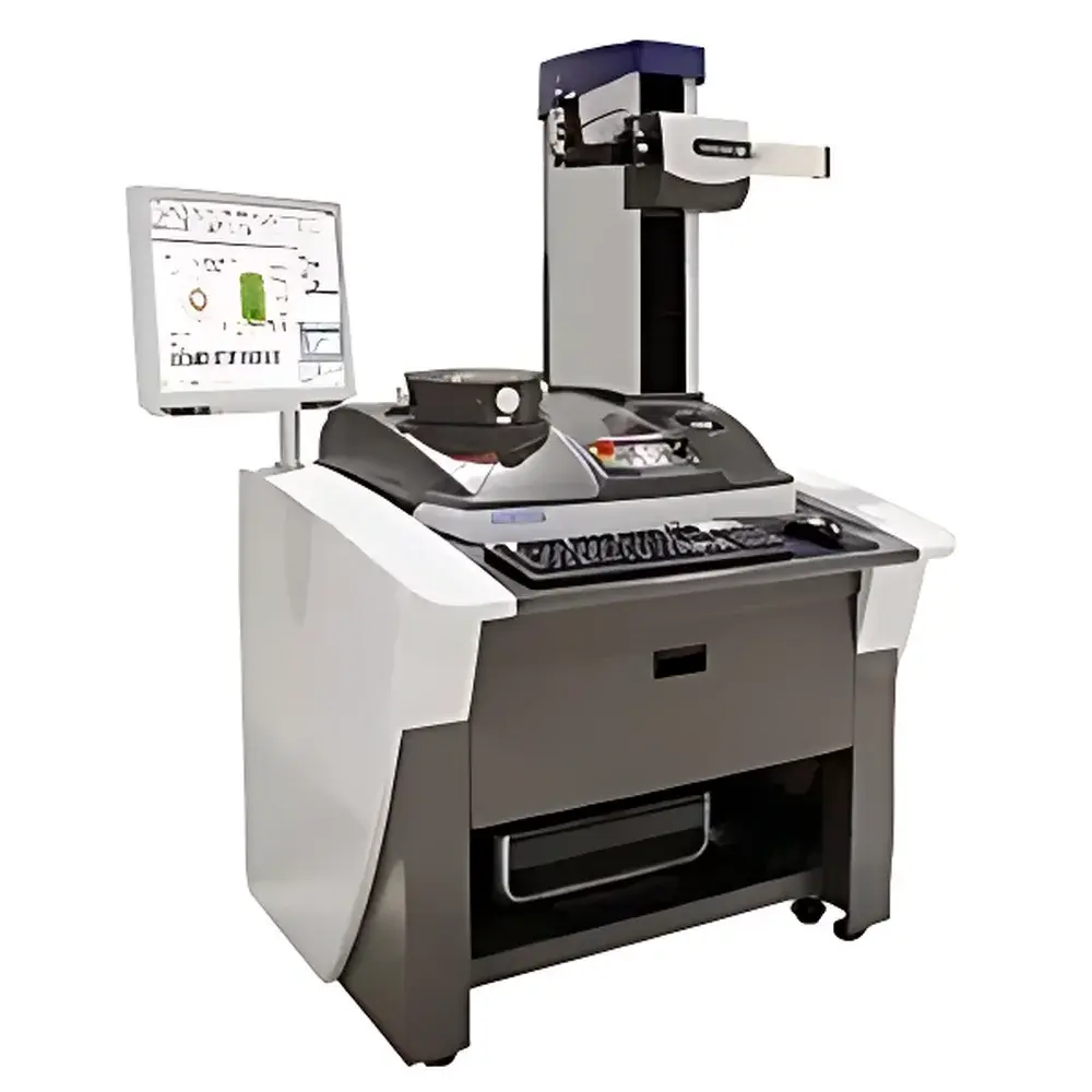
Accretech RONDCOM NEX CNC Rotational Roundness and Cylindricity Measuring System
| Brand | Accretech |
|---|---|
| Origin | Japan |
| Model | NEX |
| Measurement Range (Max. Diameter) | Φ300 mm |
| Max. Vertical Travel (Z-axis) | 300 mm / 500 mm |
| Max. Radial Travel (R-axis) | 180 mm |
| Max. Workpiece Height | 300 mm / 500 mm |
| Max. Loading Diameter | Φ580 mm |
| Max. Measuring Depth (Arm Length) | 150 mm |
| Spindle Radial Accuracy | (0.02 + 3.2H/10,000) µm per JIS B 7451-1997 (H = height in mm) |
| Spindle Axial Accuracy | (0.02 + 3.2R/10,000) µm per JIS B 7451-1997 (R = radius in mm) |
| Z-axis Straightness | 0.10 µm/100 mm (short range), 0.15 µm/300 mm (full range) |
Overview
The Accretech RONDCOM NEX is a high-precision, CNC-controlled rotational roundness and cylindricity measuring system engineered for metrology laboratories and advanced manufacturing quality assurance departments. It operates on the principle of precision spindle-based rotation combined with high-resolution vertical (Z-axis) and radial (R-axis) probing, enabling traceable, ISO-compliant evaluation of geometric form deviations—including roundness, cylindricity, straightness, concentricity, runout, and profile of line/surface. Designed to meet stringent requirements of aerospace, bearing, hydraulic component, and precision machining industries, the NEX platform delivers world-class rotational accuracy—verified per JIS B 7451-1997—and supports full 3D surface topography reconstruction through synchronized multi-axis motion control.
Key Features
- Ultra-high spindle accuracy: Radial error motion specified as (0.02 + 3.2H/10,000) µm and axial error motion as (0.02 + 3.2R/10,000) µm, where H and R are measurement height and radius in millimeters—ensuring sub-micron fidelity across full working envelopes.
- Dual-column modular architecture: Available in DX (standard height) and SD (high-column) configurations, supporting vertical travel up to 500 mm and maximum workpiece loading diameter of Φ580 mm for large-diameter shafts and housings.
- R-axis contour tracking: Real-time Z-axis compensation during rotation enables accurate measurement of tapered and conical geometries exceeding conventional sensor stroke limits.
- Opposed-diameter measurement mode: Simultaneous dual-probe acquisition or sequential high-accuracy internal/external diameter evaluation with thermal drift compensation and probe calibration traceability.
- Spiral scanning path generation: Automated helical trajectory execution for full-cylinder surface mapping—essential for evaluating thread flank geometry, bearing raceway waviness, and axial form variation.
- Integrated environmental monitoring: Optional temperature, humidity, and vibration sensors feed real-time data into measurement uncertainty calculations per ISO/IEC 17025 guidelines.
Sample Compatibility & Compliance
The RONDCOM NEX accommodates a broad spectrum of machined components—from miniature precision pins (Φ3 mm) to large-diameter hydraulic cylinders (Φ580 mm) and tall gear blanks (up to 500 mm height). Its rigid granite base, air-bearing spindle, and low-noise linear guides ensure mechanical stability under controlled laboratory conditions (20 ± 1 °C, <50% RH). All measurement algorithms and reporting outputs conform to international standards including ISO 1101 (Geometrical Product Specifications), ISO 12181 (Roundness), ISO 12180 (Cylindricity), and JIS B 7451. System validation protocols support GLP/GMP audit readiness and are compatible with FDA 21 CFR Part 11–compliant electronic record workflows when integrated with certified LIMS environments.
Software & Data Management
The proprietary RONDCOM Navigator software provides a unified interface for setup, measurement execution, analysis, and report generation. It features automated parameter optimization based on part geometry, real-time deviation visualization using color-mapped polar and Cartesian plots, and customizable GD&T reporting templates aligned with ASME Y14.5 and ISO GPS conventions. Raw data (including full point-cloud XYZ coordinates and probe deflection signals) is stored in vendor-neutral ASCII and HDF5 formats. Audit trails log all operator actions, calibration events, and software updates—meeting ISO/IEC 17025 clause 7.7 and EU Annex 11 requirements for data integrity. Optional API integration enables bidirectional communication with MES and ERP platforms via RESTful web services.
Applications
- Aerospace turbine shafts: Evaluation of journal roundness, taper, and axial runout under load-simulated mounting conditions.
- Bearing raceways: Full-surface cylindricity assessment with spiral scan paths to detect harmonic errors and grinding marks.
- Medical implant stems: Verification of surface form compliance for ASTM F2516 and ISO 14242-1 fatigue-critical geometries.
- Optical lens mounts: Sub-micron verification of mounting bore cylindricity and face-to-bore perpendicularity.
- Automotive transmission gears: Analysis of pitch circle eccentricity and tooth profile alignment prior to honing.
<liHydraulic pump components: High-resolution measurement of cylinder bore straightness and concentricity relative to flange faces.
FAQ
What standards does the RONDCOM NEX comply with for calibration and reporting?
The system adheres to JIS B 7451-1997 for spindle accuracy verification and supports measurement reporting per ISO 12181, ISO 12180, ISO 1101, and ASME Y14.5. Calibration certificates are traceable to NMIJ (National Metrology Institute of Japan) or equivalent NMIs.
Can the NEX measure internal diameters and deep bores?
Yes—using extended-stem probes and optional R-axis tracking, it measures internal diameters up to Φ300 mm and depths up to 150 mm (arm-length dependent), with automatic compensation for probe overhang and thermal expansion.
Is spiral scanning supported for full-cylinder evaluation?
Yes—the CNC motion controller executes programmable helical paths with adjustable pitch and resolution, enabling comprehensive 3D surface characterization for cylindrical parts requiring full-envelope inspection.
How is measurement uncertainty quantified and documented?
Uncertainty budgets are generated per GUM (JCGM 100:2008) incorporating contributions from spindle error, probe hysteresis, environmental drift, and software algorithm repeatability—automatically appended to PDF reports.
Does the system support automated pass/fail decision logic against GD&T tolerances?
Yes—Navigator software allows definition of tolerance zones per feature control frame, with real-time pass/fail flagging, SPC charting, and export to statistical process control platforms.