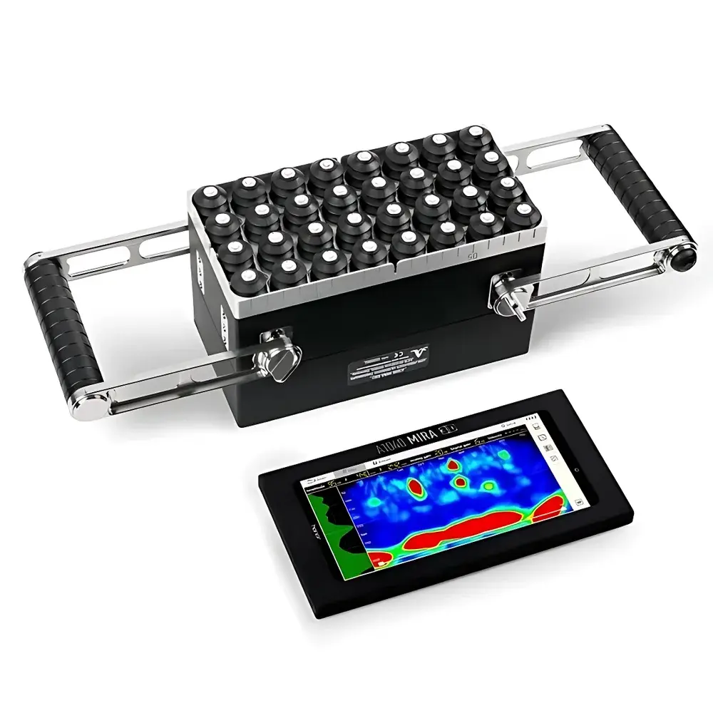
ACS A1040 MIRA 3D Concrete 3D Ultrasonic Imaging System
| Brand | ACS |
|---|---|
| Origin | Italy |
| Manufacturer Type | Authorized Distributor |
| Origin Category | Imported |
| Model | A1040 MIRA 3D |
| Frequency Bandwidth | 10–100 kHz |
| Parallel DAQ Channels | 32 |
| Maximum Penetration Depth | 3 m (concrete-dependent) |
| Maximum Coverage Area | 10 × 10 m |
| Frame Rate | 25 Hz (2D), 2 Hz (3D) |
| Battery Life | Up to 10 h per charge |
| Sensor Configuration | 4 × 8 A-DPC® array (expandable) |
| Compliance | T/CECS XXX-202X, JGJ/T 485-2019, DB32/T 3754-2020, DB34/T 5072-2017, DB37/T 5106-2018, DG/TJ 08-2252-2018, DB13(J)/T 8327-2019, DBJ/T-199-2020 |
Overview
The ACS A1040 MIRA 3D Concrete 3D Ultrasonic Imaging System is a high-resolution, non-destructive evaluation (NDE) platform engineered for quantitative structural assessment of reinforced and precast concrete elements. It employs full-matrix capture (FMC) acquisition combined with total focusing method (TFM) reconstruction to generate volumetric ultrasonic data sets—enabling true 3D tomographic visualization of internal features without mechanical scanning or time-consuming point-by-point interrogation. Unlike conventional pulse-echo or pitch-catch configurations, the A1040 MIRA 3D utilizes independent transmit-receive channels for each sensor element in its A-DPC® (Active Dry Point Contact) array, allowing simultaneous excitation and reception across all 32 parallel channels. This architecture supports real-time volumetric imaging at frame rates up to 2 Hz for full 3D reconstructions and 25 Hz for 2D cross-sectional views. The system operates within a 10–100 kHz frequency band optimized for deep penetration and resolution balance in heterogeneous concrete media—capable of detecting voids, delaminations, honeycombing, grout deficiencies in post-tensioning ducts, and quantifying crack depth and orientation with sub-centimeter spatial fidelity.
Key Features
- True3D® Tomographic Imaging: Real-time FMC/TFM volumetric reconstruction at each probe position—no interpolation or stitching required.
- A-DPC® Dry-Point Contact Sensors: Patented low-noise, spring-loaded piezoelectric transducers enabling stable coupling on rough, dusty, or slightly damp concrete surfaces without couplant.
- Expandable Aperture Architecture: Modular 4 × 8 sensor arrays can be combined into larger synthetic apertures (e.g., dual or triple array setups) to increase lateral resolution and signal-to-noise ratio.
- Depth-Enhanced Transmission Mode: Programmable high-energy pulse generation improves signal penetration in low-frequency, high-attenuation concrete—validated up to 3 m in standard C30/C40 mixes.
- Multi-Mode Imaging Engine: Supports area-scan, panoramic B-scan, panoramic D-scan, and C-scan synthesis—all accessible via intuitive touchscreen interface on tablet or laptop.
- GPU-Accelerated Processing: Onboard FPGA + NVIDIA GPU architecture enables near-real-time TFM image formation and on-the-fly defect sizing.
- Field-Deployable Design: Ruggedized electronics unit, IP54-rated enclosure, hot-swappable 18650 Li-ion battery packs (6 units included), and integrated tablet PC with protective housing.
Sample Compatibility & Compliance
The A1040 MIRA 3D is validated for use on cast-in-place, precast, prestressed, and ultra-high-performance concrete (UHPC) substrates with compressive strengths ranging from 20 MPa to over 120 MPa. Its A-DPC® sensors accommodate surface roughness up to 3 mm Ra and tolerate ambient temperatures from −10 °C to +50 °C. The system complies with Chinese national and provincial technical standards for prefabricated concrete structure inspection—including T/CECS XXX-202X, JGJ/T 485-2019, and eight regional codes (DB32/T 3754-2020 through DBJ/T-199-2020). While not certified to ASTM E2700 or ISO 19289, its FMC/TFM methodology aligns with the physical principles underpinning those standards for volumetric ultrasonic characterization. Data traceability meets GLP-aligned documentation requirements, with timestamped acquisition logs, operator ID tagging, and configurable audit trails in INTROVIEW® Pro.
Software & Data Management
INTROVIEW® Pro is a Windows- and Android-compatible desktop application providing complete control over acquisition, reconstruction, visualization, and reporting. It supports DICOM-compliant export, CSV-based defect coordinate tables, and PDF report generation with embedded 3D isosurfaces and orthogonal slice overlays. All raw FMC datasets are stored in HDF5 format with metadata headers including sensor geometry, gain settings, time-of-flight calibration, and environmental conditions. The software implements role-based access control, electronic signature support, and optional 21 CFR Part 11 compliance modules (available under extended service agreement). Remote firmware updates, spectral analysis tools, and customizable measurement templates (e.g., crack depth vs. width regression models) are included in the base license, with 12 months of priority technical support and version upgrades.
Applications
- Quality assurance of tunnel lining grouting integrity and void mapping behind segmental rings.
- In-service inspection of bridge decks, piers, and abutments for subsurface delamination and rebar corrosion-induced spalling precursors.
- Verification of embedment depth and continuity of shear connectors in composite steel-concrete systems.
- Pre- and post-stressing assessment of duct grouting completeness in post-tensioned beams and slabs.
- Non-destructive validation of connection joints in modular precast buildings per assembly tolerance specifications.
- Forensic investigation of early-age cracking mechanisms via 3D crack network topology analysis.
- Calibration and validation of numerical models (e.g., finite element simulations of wave propagation in heterogeneous media).
FAQ
What concrete properties most influence maximum penetration depth?
Penetration is primarily affected by aggregate size distribution, water-cement ratio, presence of reinforcing steel, and degree of carbonation. In typical C30–C50 concrete with ≤20 mm aggregate and minimal rebar interference, reliable detection of ≥5 mm voids is achievable at depths up to 2.5–3.0 m.
Can the A1040 MIRA 3D distinguish between air-filled voids and water-saturated defects?
Yes—through comparative analysis of amplitude attenuation, phase velocity dispersion, and frequency-dependent scattering signatures across the 10–100 kHz band. Water-saturated regions exhibit lower acoustic impedance contrast and reduced high-frequency scattering compared to air-filled cavities.
Is external calibration required before each inspection?
No—each A-DPC® sensor undergoes factory calibration against NIST-traceable reference blocks. Field verification uses the supplied aluminum reference block with machined flat-bottom holes (FBH) of known diameters and depths; automated calibration routines validate time-of-flight linearity and gain consistency across all 32 channels.
Does the system support automated defect classification?
INTROVIEW® Pro includes rule-based thresholding and region-growing algorithms for preliminary void/delamination labeling. Fully automated AI-assisted classification (e.g., CNN-based segmentation) is available as an optional module under separate licensing.
How is positional accuracy maintained during large-area scans?
Integrated IMU (inertial measurement unit), optical encoder wheels, and optional UWB (ultra-wideband) positioning anchors enable sub-5 mm spatial registration across 10 × 10 m coverage zones—without requiring external laser trackers or survey-grade GNSS.


