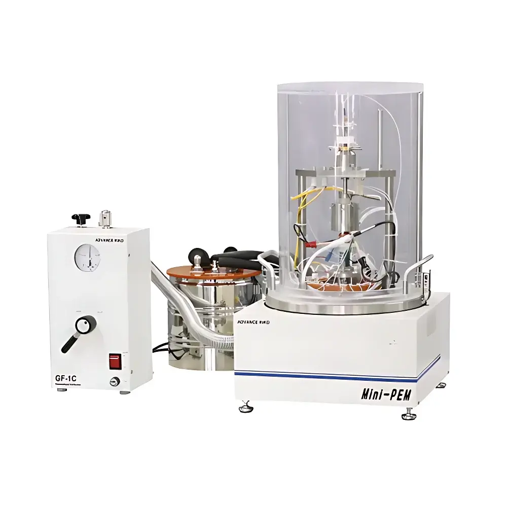
ADVANCE RIKO Mini-PEM Thermoelectric Conversion Efficiency Measurement System
| Brand | ADVANCE RIKO |
|---|---|
| Origin | Japan |
| Manufacturer Type | Authorized Distributor |
| Import Status | Imported |
| Model | Mini-PEM |
| Price Range | USD 85,000 – 170,000 |
Overview
The ADVANCE RIKO Mini-PEM Thermoelectric Conversion Efficiency Measurement System is a compact, laboratory-grade instrument engineered for the quantitative evaluation of thermoelectric (TE) material performance under controlled thermal and electrical boundary conditions. It operates on the fundamental principle of simultaneous, synchronized measurement of electrical power output (via four-point probe DC current–voltage characterization) and axial heat flow (via calibrated heat flux sensors embedded in guarded, low-thermal-resistance sample holders). From these primary measurements—open-circuit voltage (Voc), short-circuit current (Isc), electrical resistance (R), and steady-state heat flow rate (Q)—the system computes the dimensionless figure of merit (ZT) and, critically, the absolute thermoelectric conversion efficiency (η), defined as η = (Pelec/Qin) × 100%, where Pelec is net electrical power delivered to an optimized load and Qin is the total heat input across the temperature gradient. Designed for benchtop deployment, the Mini-PEM supports precise ΔT control from 20 K to 300 K with dual-zone Peltier modules and integrated Pt-100 temperature monitoring at both hot and cold interfaces (±0.1 K stability).
Key Features
- Integrated dual-sensor architecture: Simultaneous acquisition of electrical output (four-terminal sensing, ±0.02% full-scale accuracy) and directional heat flux (thermopile-based heat flux meter, calibrated traceably to NIST standards)
- Modular sample stage: Accommodates bulk TE materials (5 mm × 5 mm × 1–3 mm), pressed pellets, and thin-film stacks with standardized Cu–Cu thermocouple contact pads
- Programmable thermal profiling: Independent hot-side and cold-side temperature control (−40 °C to +200 °C), enabling ZT mapping across multiple ΔT steps per test cycle
- Load-matching optimization algorithm: Automatically determines maximum power point (MPP) by sweeping external resistive loads and calculating real-time power curves
- Robust mechanical design: Stainless-steel vacuum-compatible chamber (optional) with low-thermal-leakage gasketing and electromagnetic shielding for low-noise microvolt-level signal integrity
- Compliance-ready firmware: Supports audit trails, user access levels, and electronic signatures aligned with GLP and ISO/IEC 17025 documentation requirements
Sample Compatibility & Compliance
The Mini-PEM accepts standard thermoelectric geometries including n-type and p-type bismuth telluride (Bi2Te3), skutterudites, half-Heuslers, Mg2Si-based composites, and emerging organic–inorganic hybrids. Sample mounting follows ASTM D7984–16 guidelines for thermal interface resistance minimization. All thermal sensors are certified per ISO 8301 (hot-wire method) and calibrated against reference standards maintained under JIS Z 8000-0:2020 traceability. Electrical measurement circuits conform to IEC 60584-1 for thermocouple linearity and IEEE Std 112 for DC resistance metrology. The system meets CE marking requirements for EMC Directive 2014/30/EU and Low Voltage Directive 2014/35/EU.
Software & Data Management
The proprietary PEM-Control Suite (v4.2+) provides real-time visualization of V–I curves, dV/dT slopes, thermal resistance evolution, and cumulative η vs. ΔT plots. Raw data streams are saved in HDF5 format with embedded metadata (operator ID, timestamp, calibration certificate IDs, environmental logs). Export options include CSV, MATLAB .mat, and PDF reports compliant with FDA 21 CFR Part 11 for electronic records—featuring immutable audit trails, role-based permissions, and configurable electronic signature workflows. Batch processing scripts enable automated ZT interpolation using the Harman method or iterative numerical integration of Seebeck coefficient (S), electrical conductivity (σ), and thermal conductivity (κ) derived from primary measurements.
Applications
- Quantitative benchmarking of novel TE compounds against state-of-the-art Bi2Te3 and PbTe references under identical thermal boundary conditions
- Accelerated lifetime testing: Monitoring degradation of η and interfacial contact resistance over 500+ thermal cycles (ΔT = 150 K, ramp rate = 2 K/min)
- Module-level validation: Characterizing segmented or functionally graded TE legs to identify parasitic losses at junctions
- Thermal interface optimization: Evaluating paste, solder, and sintered metallization layers via comparative thermal resistance (Rth) analysis
- Academic research support: Enabling direct experimental validation of ab initio ZT predictions and phonon-scattering models
FAQ
Does the Mini-PEM measure thermal conductivity (κ) directly?
No. κ is derived indirectly using the measured Seebeck coefficient (S), electrical conductivity (σ), and calculated ZT via the relation ZT = (S²σT)/κ. Users must supply independent κ data—or perform complementary laser flash analysis—for full decoupling.
Can it evaluate flexible or fibrous TE materials?
Yes, with custom sample holders; however, planar geometry and uniform cross-section are prerequisites for valid heat flux interpretation per Fourier’s law assumptions.
Is vacuum operation supported out of the box?
The base configuration operates in ambient air. A vacuum-compatible upgrade kit (including O-ring sealed chamber and feedthroughs for thermocouples and current leads) is available as an optional accessory.
What calibration standards accompany the system?
Each shipment includes NIST-traceable calibration certificates for heat flux sensors and a certified reference TE module (Bi2Te3, known ZT @ 300 K) for daily performance verification.
How is electrical contact resistance minimized during four-probe measurement?
By employing spring-loaded, gold-plated tungsten carbide probes with <10 µΩ contact resistance, coupled with automatic offset compensation routines executed prior to each measurement sequence.


