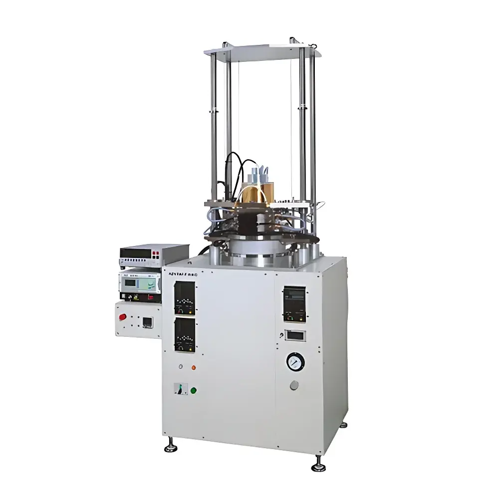
ADVANCE RIKO PEM-2 Thermoelectric Conversion Efficiency Measurement System
| Brand | ADVANCE RIKO |
|---|---|
| Origin | Japan |
| Model | PEM-2 |
| Maximum Temperature Gradient | 500 °C (up to 800 °C heating surface) |
| Sample Geometry | Square, 20/30/40 mm × 5–30 mm thickness |
| Contact Pressure | 2 MPa (at 30 mm square sample) |
| Atmosphere | Inert gas compatible |
| Measurement Method | One-dimensional heat flux input method |
| Measured Parameters | Thermoelectric conversion efficiency (η), electrical power output (P), thermal input flux (Q) |
| Heating System | High-precision infrared gold-mirror furnace |
| Cooling System | Integrated water-cooled lower stage |
| Load Control | Automated variable resistive load adjustment |
| Software | Fully integrated control with thermal stability detection, real-time data logging, and automated test sequencing |
Overview
The ADVANCE RIKO PEM-2 Thermoelectric Conversion Efficiency Measurement System is an engineered platform for direct, standardized determination of the thermoelectric energy conversion efficiency (η) of bulk modules and segmented devices under realistic thermal operating conditions. Unlike indirect estimation methods relying on Seebeck coefficient, electrical conductivity, and thermal conductivity measurements—each subject to cumulative uncertainty—the PEM-2 implements the one-dimensional heat flux input method in accordance with ISO 14405-1 and ASTM E3079 guidelines for thermoelectric module characterization. It establishes a controlled, steady-state temperature gradient across the sample while simultaneously measuring total thermal input (Q), net electrical output (P), and interfacial thermal resistance—enabling calculation of η = P/Q with traceable metrological integrity. The system accommodates standard square geometries (20–40 mm side length, 5–30 mm thickness) and supports operation up to 800 °C at the hot-side surface, with a maximum sustainable ΔT of 500 °C between top and bottom interfaces under inert atmosphere.
Key Features
- High-fidelity infrared gold-mirror furnace with rapid thermal response and spatial uniformity ≤ ±1.5 °C over 30 mm diameter zone—enabling precise thermal profiling and accelerated lifetime evaluation via repeated thermal cycling.
- Dual-zone thermal architecture: Upper radiant heater and lower water-cooled stage maintain stable, reproducible thermal boundary conditions; contact pressure is actively regulated via pneumatic cylinder to minimize interfacial thermal resistance drift during extended tests.
- Integrated real-time load optimization: Software-controlled variable resistive load bank automatically sweeps and locks at maximum power point (MPP) for each temperature step, ensuring accurate Pmax capture without manual intervention.
- Automated thermal stabilization protocol: Algorithm-based detection of steady-state conditions (dΔT/dt < 0.02 °C/min for ≥5 min) triggers measurement sequence—eliminating subjective operator judgment and enhancing inter-laboratory repeatability.
- Modular mechanical design compliant with ISO/IEC 17025 calibration traceability requirements; all temperature sensors (Type K thermocouples, calibrated to ±0.5 °C) and load cells are accessible for third-party verification.
Sample Compatibility & Compliance
The PEM-2 accepts sintered, segmented, or bonded thermoelectric modules with planar geometry and metallized top/bottom electrodes. Standard configurations include 20 mm × 20 mm, 30 mm × 30 mm, and 40 mm × 40 mm footprints, with thickness ranging from 5 to 30 mm. Contact pressure is mechanically constrained to 2 MPa for 30 mm samples—sufficient to ensure low-contact-resistance interfaces without inducing microstructural deformation in brittle chalcogenides or skutterudites. All testing occurs under purified argon or nitrogen (≤10 ppm O2) to prevent oxidation of Bi2Te3, Mg2Si, or half-Heusler compounds. The system meets essential safety and electromagnetic compatibility requirements per IEC 61000-6-3 and IEC 61010-1, and its measurement workflow supports GLP-compliant audit trails when used with optional 21 CFR Part 11–enabled software licensing.
Software & Data Management
The proprietary PEM-Control Suite provides full instrument orchestration through a deterministic real-time kernel. It supports synchronized acquisition of 16-channel thermocouple data, four-quadrant power electronics feedback, and digital load position encoding at 100 Hz sampling. Raw datasets are stored in HDF5 format with embedded metadata (sample ID, ambient RH/T, gas flow rate, calibration certificate IDs). Post-processing modules implement ISO 14405-1–aligned efficiency calculation, thermal resistance decomposition (Rth,contact vs. Rth,bulk), and Arrhenius-based degradation modeling for thermal cycling studies. Export options include CSV, MATLAB .mat, and PDF reports conforming to journal submission standards (e.g., Energy & Environmental Science, Nature Communications).
Applications
- Direct validation of η for high-ZT materials (e.g., SnSe, Cu2Se, YbAl3) under industrially relevant ΔT conditions—bridging the gap between laboratory-scale property measurement and module-level performance forecasting.
- Accelerated reliability assessment via programmable thermal cycling (−50 °C to 600 °C, ramp rates 1–10 °C/min) with in-situ efficiency tracking to identify failure onset mechanisms (interdiffusion, electrode delamination, grain boundary oxidation).
- Interfacial engineering studies: Quantification of contact resistance contributions to total thermal impedance using iterative pressure–efficiency mapping at fixed ΔT.
- Validation benchmarking for multi-physics simulation tools (e.g., COMSOL Multiphysics® thermoelectric modules) by providing boundary-condition-constrained experimental η(ΔT) curves.
- Support for international round-robin testing initiatives coordinated by IEA TCP Annex 21 and the Thermoelectric Materials Evaluation Consortium (TEMEC).
FAQ
How does the PEM-2 differ from Seebeck coefficient-only measurement systems?
The PEM-2 measures end-to-end energy conversion—not just material transport properties—by imposing realistic thermal gradients and quantifying actual power delivery under matched load conditions.
Can the system accommodate non-square or flexible thermoelectric generators?
Standard fixtures are designed for rigid square modules; custom tooling is available for rectangular or annular geometries upon engineering review.
Is calibration documentation provided with the system?
Yes—NIST-traceable calibration certificates for all primary sensors (thermocouples, load cells, current shunts) are delivered with initial commissioning and updated annually per ISO/IEC 17025 protocols.
What inert gas flow rate is required for stable operation at 800 °C?
Minimum purge flow is 1.2 L/min of argon (99.999% purity); mass flow controllers are integrated into the base configuration.
Does the software support automated reporting for regulatory submissions?
With optional 21 CFR Part 11 compliance package, the system provides electronic signatures, audit logs, and locked report generation suitable for FDA or EU MDR submissions.


