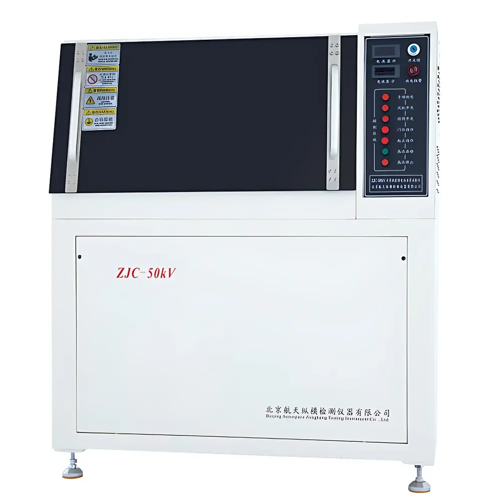
Aerospace ZJC-100KV AC/DC Dielectric Withstand & Breakdown Voltage Tester
| Brand | Aerospace |
|---|---|
| Origin | Beijing, China |
| Model | ZJC-100KV |
| Max Output Voltage | 100 kV (AC/DC) |
| Input Voltage | AC 220 V ±10%, 50 Hz |
| Power Rating | 5 kVA |
| Voltage Regulation | Continuous, stepless (0–3000 V/s) |
| Voltage Measurement Accuracy | ≤ ±1% |
| Test Environments | Air or Transformer Oil Immersion |
| Safety Response Time | ≤ 0.01 s for overcurrent cutoff |
| Operating Temperature | 15–30 °C |
| Relative Humidity | 0–85% RH (non-condensing) |
| Compliance | GB 1408.1–2006, GB 1408.2–2006, GB/T 1695–2005, GB/T 3333, GB 12656, ASTM D149, ASTM D876, DIN 53481, IEC 60243, UNI 4291 |
Overview
The Aerospace ZJC-100KV AC/DC Dielectric Withstand & Breakdown Voltage Tester is a precision high-voltage test system engineered for quantitative evaluation of dielectric strength and insulation integrity in solid insulating materials. It operates on the principle of controlled voltage escalation—either sinusoidal AC (50 Hz) or polarity-stable DC—to induce electrical breakdown across standardized test specimens. The instrument measures the critical electric field intensity (kV/mm) at which catastrophic loss of insulating resistance occurs, providing traceable data essential for material qualification, quality control, and regulatory compliance in electrical insulation engineering. Designed for laboratory and industrial R&D environments, it supports both short-term breakdown threshold determination and time-dependent withstand testing under sustained voltage stress—enabling assessment of aging behavior, partial discharge inception, and thermal-electrical degradation mechanisms.
Key Features
- True dual-mode operation: fully independent AC and DC high-voltage generation circuits with automatic mode recognition and safety interlock sequencing
- Stepless voltage ramp control: programmable rise rates from 100 V/s to 3000 V/s, enabling precise adherence to ASTM D149 Method A (short-time), Method B (step-by-step), and Method C (slow-rate)
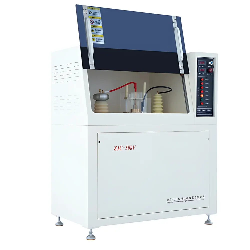
- Integrated electromagnetic shielding: laminated transparent observation window with embedded conductive mesh (≥60 dB attenuation at 1–100 MHz), compliant with IEC 61000-4-3 for operator radiation safety
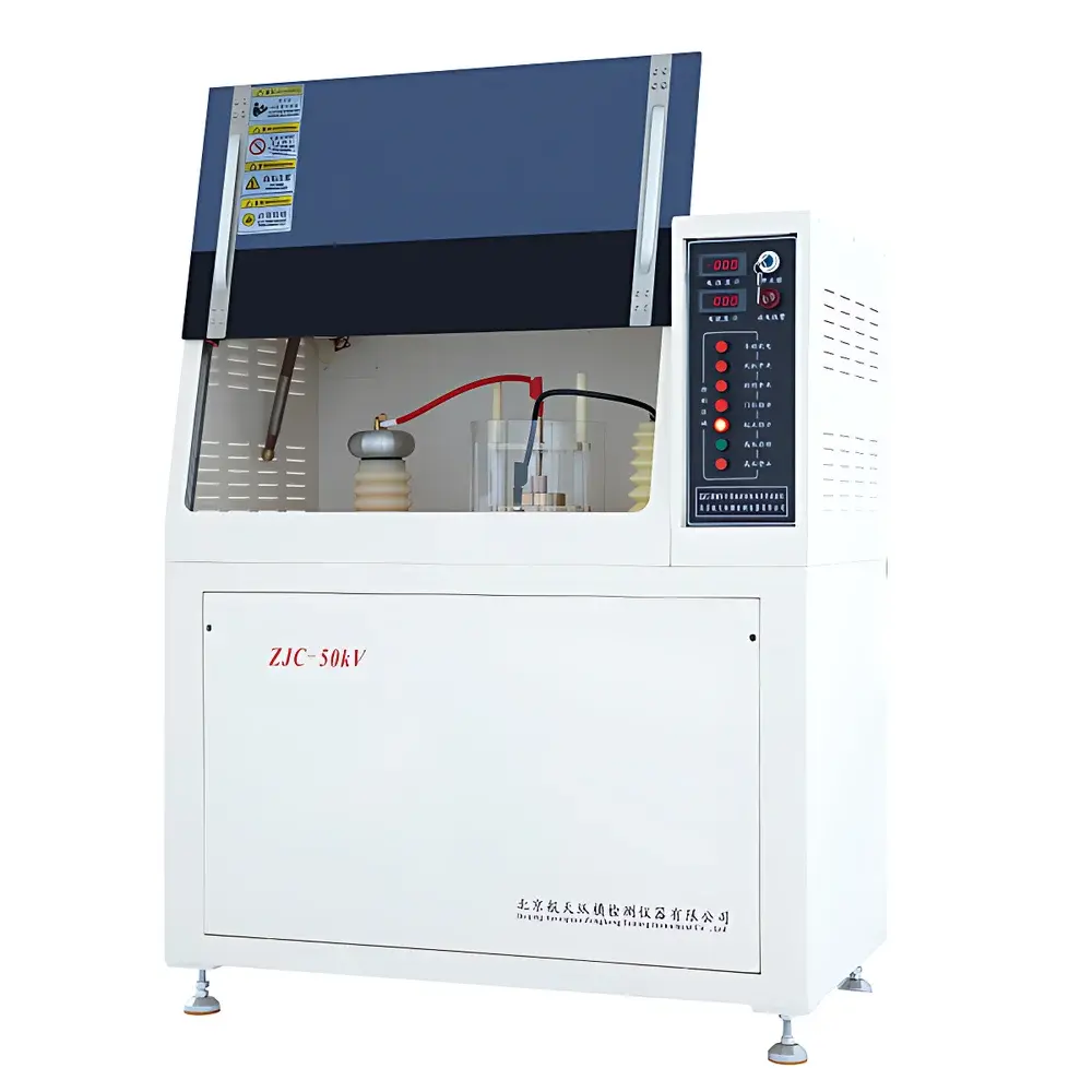
- Dual-sensor real-time monitoring: simultaneous acquisition of output voltage (±1% FS) and leakage current (resolution down to 1 µA), with configurable trip thresholds for voltage- or current-based termination
- Automated post-test discharge sequence: microprocessor-controlled grounding of HV electrodes via resistive bleeder circuit; audible/visual alarm activated if chamber door is opened before full discharge (<5 kV residual)
- Six-tier hardware safety architecture: includes main power disconnect, keyed HV isolation switch, zero-voltage enable logic, interlocked access door sensor, primary-side current limiting breaker, and dedicated RCD (residual current device)
- Embedded lighting system with adjustable intensity: cold-white LED array (5000 K CCT) mounted inside test chamber to ensure consistent visual inspection under low-ambient conditions
Sample Compatibility & Compliance
The ZJC-100KV accommodates flat-sheet, disc, and rod-shaped specimens per ISO 2577 and ASTM D149 specimen geometry requirements. Standard electrode configurations include 25 mm diameter brass discs (IEC 60243-1), 6 mm radius hemispherical electrodes (ASTM D876), and custom-configurable non-standard geometries. Testing media options are ambient air (IEC 60270-compliant for PD detection readiness) or refined mineral oil (ASTM D877/D1816). All operational protocols satisfy mandatory clauses of GB 1408.1–2006 (equivalent to IEC 60243-1), GB 1408.2–2006 (impulse testing), and USP for pharmaceutical packaging barrier validation. Full audit trail logging meets GLP/GMP documentation requirements per FDA 21 CFR Part 11 when paired with validated software configuration.
Software & Data Management
The proprietary Windows-based control suite provides ISO/IEC 17025-aligned test execution workflows. It features automated method templates for common standards (e.g., “GB1408.1_AC_Stepwise”), real-time oscillographic display of V(t) and I(t) waveforms, and export-ready datasets in CSV, XML, and PDF formats. All user actions—including parameter edits, start/stop commands, and manual overrides—are timestamped and logged with operator ID. Software enforces pre-test safety checks: chamber door status, HV zero-position verification, grounding continuity confirmation, and environmental condition validation (via optional external温湿度 sensor integration). Calibration certificates and maintenance records are stored within encrypted database partitions accessible only by authorized personnel.
Applications
- Quality assurance of polymer films (polyimide, PET, PTFE), epoxy encapsulants, and silicone rubber gaskets used in high-voltage cable joints and bushings
- Dielectric characterization of ceramic substrates (Al₂O₃, AlN) and glass-ceramic composites for power electronics packaging
- Comparative screening of nanocomposite insulators (e.g., SiO₂/Epoxy, BN/Polypropylene) under accelerated aging protocols
- Validation of conformal coatings on PCB assemblies per IPC-CC-830B and MIL-I-46058C
- Research into space charge accumulation dynamics in XLPE cables using DC ramp-and-hold protocols
- Compliance testing of medical device insulation barriers per IEC 60601-1 Clause 8.8.3
FAQ
What is the maximum recommended test voltage for routine calibration verification?
The system is rated for continuous operation up to 100 kV. For metrological traceability, annual calibration should be performed at three points: 20 kV, 50 kV, and 100 kV using NIST-traceable high-voltage dividers.
Can the instrument perform ramp-and-hold tests with variable dwell times?
Yes—software-defined hold periods (1 s to 6000 s) are supported after reaching target voltage, with automatic current monitoring during dwell to detect progressive breakdown.
Is oil-immersion testing compatible with all electrode types?
Only electrodes certified for oil use (e.g., brass with passivated surfaces) may be employed in transformer oil; standard air electrodes must be replaced to prevent oxidation and arcing path distortion.
How does the system handle partial discharge detection during AC testing?
While not a dedicated PD analyzer, the real-time current waveform capture (1 MS/s sampling) enables post-processing identification of repetitive micro-discharge pulses above 50 pC threshold when used with calibrated coupling capacitors.
What environmental conditions are required for ISO 293 standard-compliant testing?
Testing must occur in conditioned environment: 23 ±2 °C and 50 ±5% RH for ≥4 h prior to specimen conditioning, as specified in ISO 293 Annex B.


