Aerospace ZJD-A High-Frequency Dielectric Constant and Dissipation Factor Analyzer
| Brand | Aerospace |
|---|---|
| Origin | Beijing, China |
| Model | ZJD-A |
| Frequency Range | 10 kHz – 110 MHz |
| Q Measurement Range | 1–1000 |
| Tanδ Accuracy | 1×10⁻⁴ |
| εr Accuracy | 0.001 |
| Electrode Diameter | Φ38 mm or Φ50 mm (selectable) |
| Electrode Spacing Adjustment | ≥15 mm |
| Sample Thickness Range | 0.1–10 mm |
| Residual tanδ of Fixture | ≤4×10⁻⁴ @ 1 MHz |
| Power Supply | 220 V ±10%, 50 Hz ±2.5 Hz |
| Operating Temperature | 0–40 °C |
| Power Consumption | ~25 W |
| Compliance | GB/T 1409–2006, GB/T 1693–2007, ASTM D150–11, IEC 60250 |
Overview
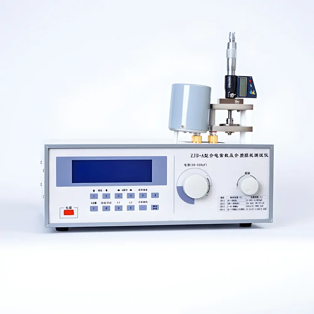
The Aerospace ZJD-A High-Frequency Dielectric Constant and Dissipation Factor Analyzer is a precision instrument engineered for the quantitative characterization of dielectric properties in solid and thin-film insulating materials under high-frequency alternating electric fields. It operates on the principle of series-resonant cavity perturbation using a calibrated parallel-plate capacitor fixture coupled with a digitally synthesized Q-meter. The system measures the shift in resonant frequency and Q-factor (quality factor) induced by insertion of a dielectric sample between the electrodes, enabling calculation of complex permittivity—specifically the relative static dielectric constant (εr) and the loss tangent (tan δ)—according to established electromagnetic theory for low-loss dielectrics. Designed for laboratory-based quality control, R&D validation, and material specification compliance, the ZJD-A delivers traceable, repeatable measurements across a broad frequency span (10 kHz to 110 MHz), supporting both narrowband discrete-frequency analysis and broadband resonance scanning.
Key Features
- DDS-based digital signal source with 6-digit frequency resolution and stability of ±3×10⁻⁵, ensuring reproducible excitation across 11,000:1 frequency coverage ratio
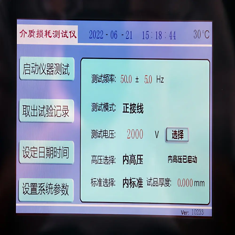
- Automated resonance search and Q-value tracking with real-time display of F, L, C, Q, LT, CT, and band status on integrated LCD
- Dual-electrode configuration with interchangeable Φ38 mm and Φ50 mm parallel plates, adjustable spacing ≥15 mm, and micrometer-driven thickness control (0.001 mm resolution)
- Integrated residual inductance compensation and large-capacitance direct-readout functionality for enhanced measurement integrity
- Q-range auto-ranging across five decades (30/100/300/1000) with <5% measurement uncertainty and 0.1 Q-resolution
- Capacitance measurement range from 1 pF to 2.5 µF; inductance range from 1 nH to 8.4 H; main tuning capacitance 30–540 pF
- Fixture-specific calibration traceability: residual tan δ ≤4×10⁻⁴ at 1 MHz, validated per IEC 60250 Annex B procedures
Sample Compatibility & Compliance
The ZJD-A supports standardized testing of rigid, semi-rigid, and flexible sheet materials—including FR-4 PCB laminates, PTFE, polyimide films, epoxy resins, silicone thermal interface pads, quartz glass, alumina ceramics, OCA optical adhesives, and engineering thermoplastics (e.g., PA, PC, PMMA, PS, PVC). Sample thickness must fall within 0.1–10 mm, and surface flatness must meet ISO 2431 requirements for parallel-plate geometry. All measurements adhere to internationally recognized test protocols: GB/T 1409–2006 (equivalent to IEC 60250), GB/T 1693–2007 (rubber-specific adaptation), ASTM D150–11 (solid electrical insulators), and GBT 5594.4–2015 (electronic structural ceramics). The instrument’s mechanical design, electrode finish, and thermal management conform to GLP-aligned environmental operating conditions (0–40 °C, <80% RH non-condensing).
Software & Data Management
While the ZJD-A operates as a standalone hardware platform, its optional software module—compatible with ZJD-A/B or ZJD-C host units—enables automated data acquisition, εr/tan δ computation, and export to CSV or Excel formats. The embedded algorithm applies standard correction factors for fringing field effects and electrode edge capacitance, referencing NIST-traceable calibration constants stored in non-volatile memory. Audit trails include timestamped measurement logs, operator ID fields (when integrated with domain-authenticated PCs), and configurable pass/fail thresholds for Q-value screening (5–1000, with audible/visual alerts). Though not natively 21 CFR Part 11 compliant, the system supports external validation documentation packages required for ISO/IEC 17025-accredited laboratories performing dielectric testing under GMP or automotive AEC-Q200 frameworks.
Applications
- Quality assurance of high-frequency PCB substrates and RF antenna dielectrics
- Development and qualification of low-loss microwave packaging materials
- Characterization of thermal interface materials (TIMs) for power electronics cooling
- Batch-to-batch consistency verification of polymer films used in capacitors and flexible circuits
- Research into frequency-dependent dispersion behavior of nanocomposite dielectrics
- Failure analysis of moisture-induced dielectric degradation in encapsulated electronic components
- Validation of material specifications against MIL-STD-202 or IPC-TM-650 test methods
FAQ
What standards does the ZJD-A comply with for dielectric measurements?
The system is designed and verified to meet the technical requirements of GB/T 1409–2006, GB/T 1693–2007, ASTM D150–11, and IEC 60250, including fixture geometry tolerances, frequency accuracy, and Q-measurement uncertainty budgets.
Can the ZJD-A measure liquid samples?
The base configuration includes a solid-sample parallel-plate fixture only. A liquid test cell (optional LKI-1 accessory) is available separately and requires recalibration for meniscus height, electrode immersion depth, and temperature-controlled bath integration.
Is the instrument suitable for production-line use?
Yes—its robust mechanical architecture, fast auto-tuning capability (<2 s per resonance point), and intuitive front-panel interface support routine QC testing. For full traceability, pairing with external PC-based logging software is recommended.
How is electrode spacing calibrated and verified?
Spacing is adjusted via a calibrated micrometer with 1 µm resolution. Verification is performed using certified gauge blocks and confirmed through open-circuit capacitance measurement against NIST-traceable reference capacitors.
Does the system support temperature-controlled measurements?
No built-in temperature chamber is included. However, the fixture design accommodates third-party environmental chambers (e.g., Linkam TS1500) with feedthrough-compatible electrode leads and thermal isolation mounts.


