AET TM-Mode Cavity Resonator Dielectric Characterization System
| Brand | AET |
|---|---|
| Origin | Japan |
| Model | TM010/TM011 Cavity Resonator |
| Frequency Range | 1–10 GHz |
| Permittivity (ε′) | 1–30 |
| Accuracy | ±1% |
| Loss Tangent (tan δ) | 0.0001–0.05 |
| Accuracy | ±5% |
| Compliance | JIS C2565, ASTM D2520 |
| Sample Form | Rectangular bar (non-destructive) |
| Q-Factor | High (>10,000 typical) |
| Cavity Customization | Frequency-specific cavity modules available |
Overview
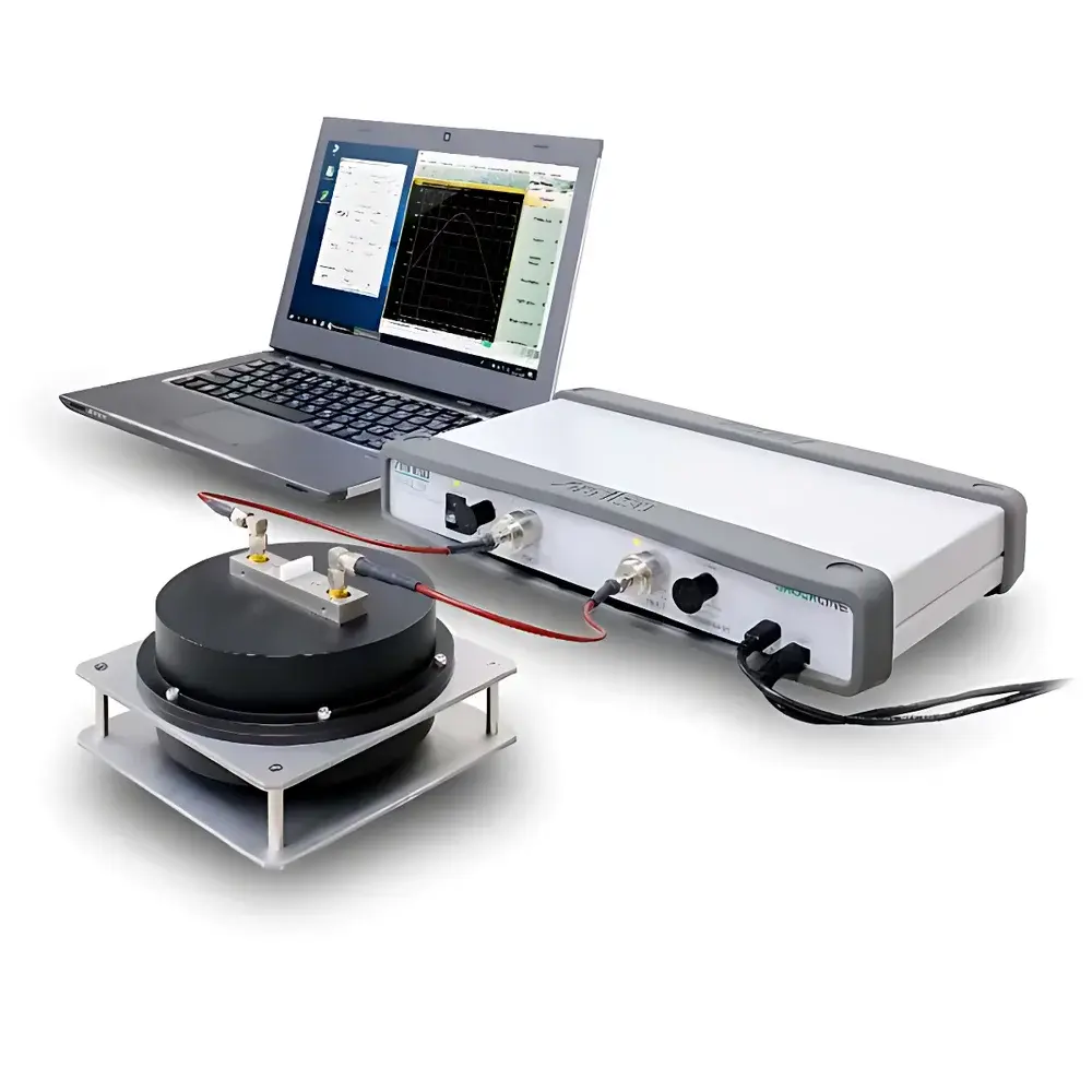
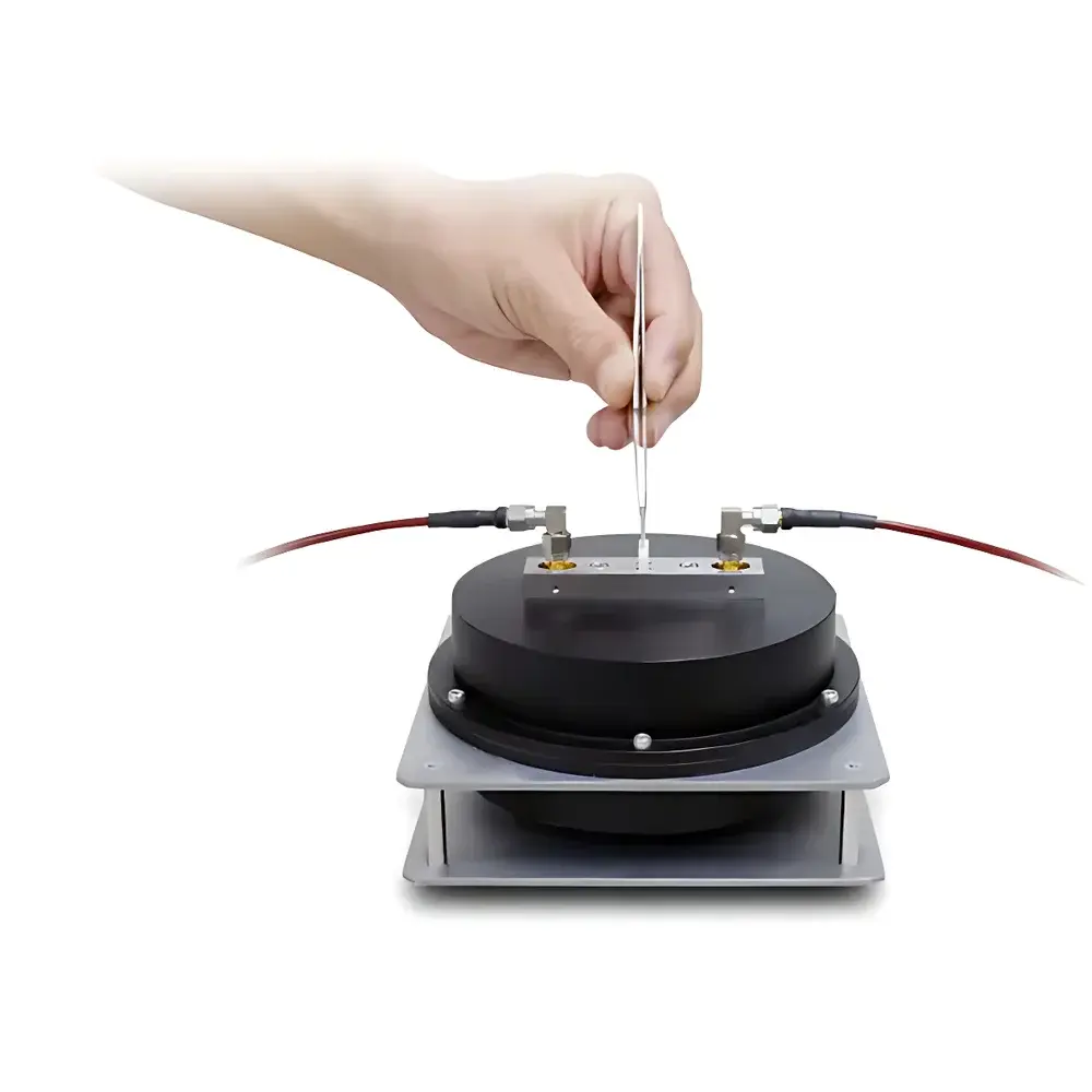
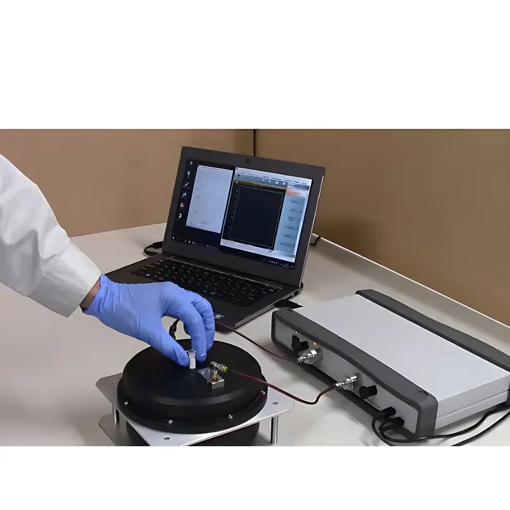
The AET TM-Mode Cavity Resonator Dielectric Characterization System is a precision metrology instrument engineered for high-resolution, non-destructive measurement of complex permittivity (ε′ and ε″) and dielectric loss tangent (tan δ) in low-loss solid dielectric materials. Operating on the fundamental principle of transverse magnetic (TM) mode resonance—specifically TM010 and TM011 modes—the system utilizes a high-Q cylindrical metallic cavity where the electric field vector is oriented parallel to the central symmetry axis. When a rectangular bar-shaped sample is inserted coaxially into the cavity’s field maximum region, perturbation of the resonant frequency (fr) and quality factor (Q) enables extraction of ε′ and tan δ via rigorous electromagnetic cavity perturbation theory. This method delivers exceptional sensitivity for materials with dissipation factors below 0.001—where conventional open-ended coaxial or free-space techniques suffer from signal-to-noise limitations. The system is purpose-built for R&D laboratories and quality control environments requiring traceable, repeatable characterization of advanced dielectrics used in high-frequency electronic substrates.
Key Features
- High-Q TM-mode resonant cavities (Q > 10,000 at 5 GHz), enabling sub-0.0001 resolution in tan δ for ultra-low-loss materials such as PTFE, fused silica, and single-crystal alumina
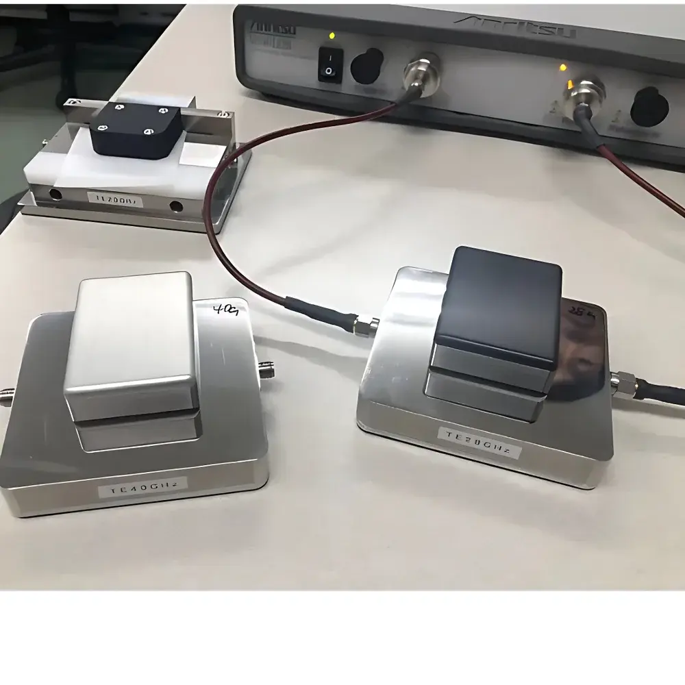
- Modular cavity design: Each cavity is optimized for a discrete frequency point within 1–10 GHz; multiple cavities can be integrated into a single platform for broadband coverage
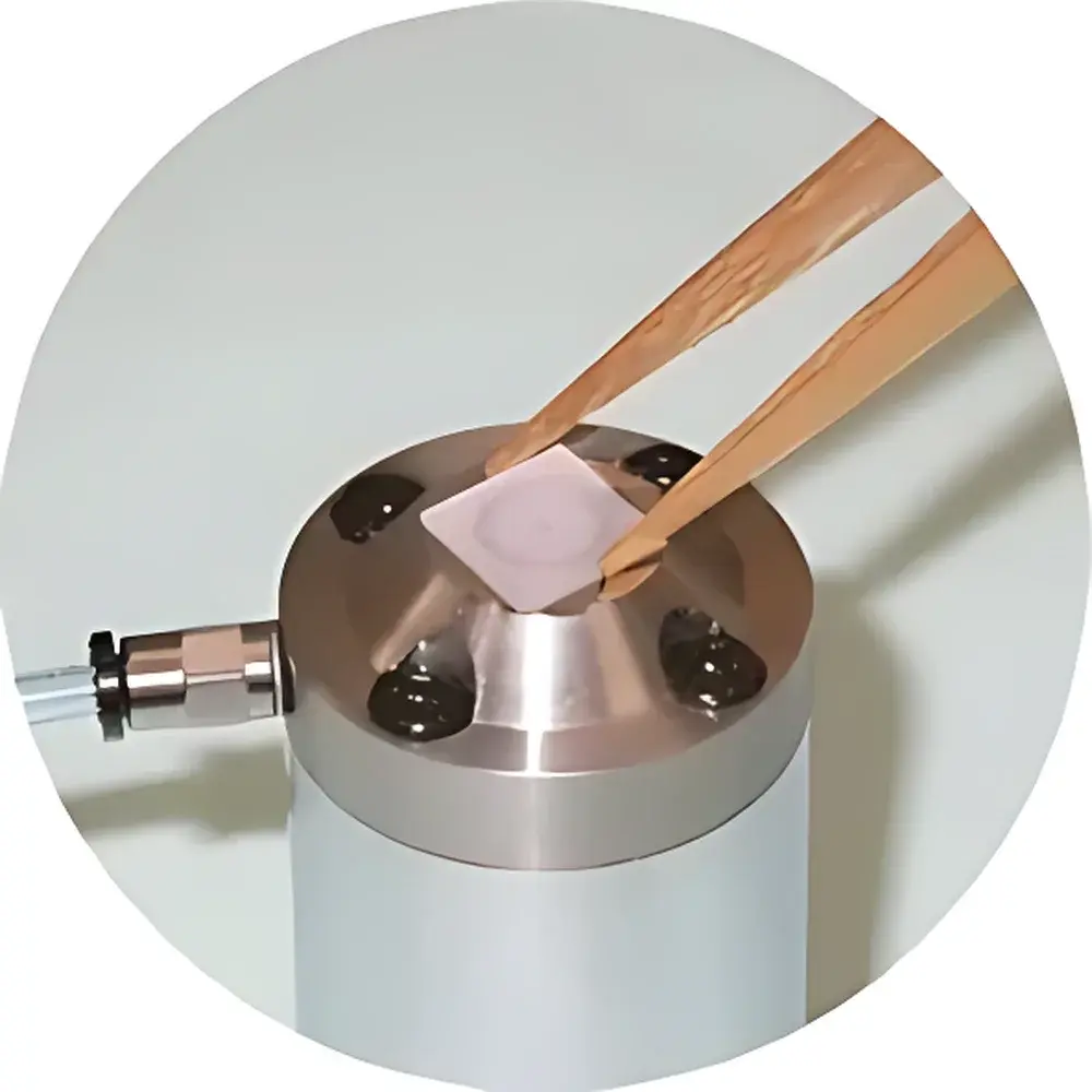
- Non-destructive, contact-free measurement geometry—no electrode deposition or sample metallization required
- Full compliance with international standard test methods: JIS C2565 (Japanese Industrial Standard for dielectric measurement of solid insulating materials) and ASTM D2520 (Standard Test Method for Dielectric Constant of Solid Electrical Insulating Materials at Microwave Frequencies)
- Thermal-stable brass or copper cavity construction with precision-machined internal surfaces to minimize surface resistance losses and ensure long-term calibration stability
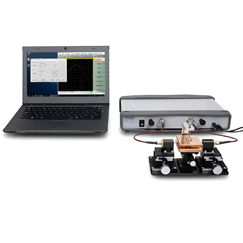
- Integrated vector network analyzer (VNA) interface for automated S-parameter acquisition (S21 transmission mode) and real-time resonance tracking
Sample Compatibility & Compliance
The system accepts rectangular bar specimens (typically 2–10 mm × 2–10 mm × 15–40 mm) cut normal to the intended field direction. It is validated for use with rigid, homogeneous, isotropic dielectrics—including laminated composites (e.g., CCLs), sintered ceramics, polymer films, semiconductor wafers, and nanostructured thin-film stacks. Samples must exhibit minimal conductivity (<10−9 S/m) and dimensional uniformity within ±0.02 mm to satisfy cavity perturbation assumptions. All measurements adhere to GLP-aligned documentation protocols, with full audit trails for frequency calibration, cavity temperature stabilization (±0.1°C), and reference material validation (e.g., fused quartz, sapphire standards). Data output conforms to ASTM E2507 requirements for reporting uncertainty budgets in dielectric metrology.
Software & Data Management
The proprietary AET CavityRes™ software provides end-to-end workflow automation—from cavity resonance search and automatic Q-factor calculation to ε′/tan δ inversion using closed-form perturbation equations. Raw VNA data (S-parameters) are stored in IEEE 1597.1-compliant HDF5 format. Software supports batch processing across multiple cavities and includes built-in uncertainty propagation per GUM (Guide to the Expression of Uncertainty in Measurement). Export options include CSV, MATLAB .mat, and PDF reports with embedded metadata (cavity ID, temperature, operator, timestamp, calibration certificate ID). For regulated environments, optional 21 CFR Part 11 compliance package adds electronic signatures, role-based access control, and immutable audit logs.
Applications
- Characterization of high-speed PCB substrate materials (e.g., polyimide, BT resin, LCP) for impedance control and signal integrity modeling
- Qualification of low-loss dielectric resonators and filter components in 5G/mmWave base station hardware
- Development and QC of antenna substrates for phased-array radar and satellite communication systems
- Dielectric screening of thin-film encapsulation layers in flexible OLED and micro-LED displays
- Process validation of atomic-layer-deposited (ALD) high-k dielectrics in advanced logic and memory devices
- Research on metamaterial unit cells and phononic crystal lattices requiring precise ε′ dispersion mapping
FAQ
What sample dimensions are required for accurate TM-mode cavity measurements?
Standard samples are rectangular bars with cross-sections of 3.0 × 3.0 mm² and lengths between 20–35 mm. Minimum length must exceed λ/4 at the target frequency to avoid higher-order mode coupling.
Can the system measure anisotropic or layered materials?
Yes—provided the principal dielectric axis aligns with the cavity’s E-field direction. For multilayer films, effective medium approximations (e.g., series-capacitance model) are supported in post-processing.
Is temperature-controlled measurement possible?
Optional cryogenic or thermostatic sample holders (−40°C to +150°C) integrate seamlessly with cavity mounts and maintain axial alignment under thermal expansion.
How often does the cavity require recalibration?
Cavity geometry is mechanically stable; annual verification against NIST-traceable reference materials (e.g., sapphire rods) is recommended per ISO/IEC 17025 guidelines.
Does the system support automated production-line integration?
Yes—via Ethernet-based SCPI command set and OPC UA server option for MES/SCADA interoperability in Industry 4.0 environments.


