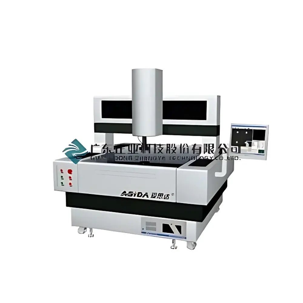
Aisida Gantry-Style 2D Vision Measuring Machine
| Brand | Aisida |
|---|---|
| Origin | Guangdong, China |
| Manufacturer Type | Authorized Distributor |
| Country of Origin | China |
| Model | Gantry-Style Vision Measuring Machine |
| Quotation | Upon Request |
| Measurement Range (X×Y×Z) | 600×500×150 mm / 700×600×150 mm / 900×600×150 mm |
| Glass Stage Size & Load Capacity | 650×550 mm / 750×650 mm / 950×650 mm |
| Objective Working Distance | 90 mm |
| Objective Magnification | 0.7×–4.5× (Optional: 0.5×, 1×, 2×) |
| Eyepiece Magnification | 0.5× (Optional: 1×, 2×) |
| Granite Base & Column Material | Natural Granite |
| Linear Accuracy | (3 + L/200) µm (L in mm) |
| Repeatability | ≤ ±3 µm |
| Encoder Resolution | ≤ 1 µm |
| Structural Configuration | Gantry-Type |
| Motion System | Panasonic AC Servo Motors |
| Guidance System | Air Bearings on Granite Ways (X/Y) |
| Illumination | Ring-shaped LED Cold Light Source |
| Imaging Sensor | High-Sensitivity CCD Camera |
Overview
The Aisida Gantry-Style 2D Vision Measuring Machine is a precision optical metrology system engineered for high-accuracy, non-contact dimensional inspection of planar components and geometric features. Based on digital image acquisition, edge detection algorithms, and calibrated coordinate metrology principles, the instrument captures high-fidelity video frames via a stabilized CCD imaging sensor mounted on a rigid gantry structure. Measurement data is derived from pixel-to-micron mapping calibrated against high-stability optical encoders, enabling traceable two-dimensional analysis of points, lines, circles, arcs, rectangles, angles, distances, profiles, and surface contours. Designed for ISO 9001-compliant quality control environments, it supports both routine first-article inspection and statistical process control (SPC) workflows in regulated manufacturing settings.
Key Features
- Natural granite base and column construction ensures long-term dimensional stability, thermal inertia, and resistance to mechanical creep—critical for sub-micron repeatability over extended operational cycles.
- Air-bearing guidance system on granite ways for X- and Y-axes eliminates mechanical friction, minimizing wear and hysteresis while maintaining consistent positioning accuracy across full travel ranges.
- Friction-driven, gearless motion transmission using precision ground linear rods guarantees smooth, backlash-free stage movement without oil contamination or particulate generation—ideal for cleanroom-compatible operation.
- Ring-type LED cold illumination delivers uniform, flicker-free coaxial and oblique lighting with negligible thermal emission, preventing heat-induced sample or stage deformation during prolonged measurement sessions.
- High-resolution optical path incorporating multi-magnification objectives (0.7×–4.5× standard, with optional 0.5×/1×/2× lenses) and matched eyepieces enables scalable field-of-view and depth-of-field optimization for diverse part geometries and surface finishes.
- Three-axis motion controlled by Panasonic AC servo motors provides synchronized, programmable positioning with real-time feedback, supporting automated measurement sequences and repeatable feature alignment.
Sample Compatibility & Compliance
The system accommodates flat, rigid, and semi-rigid specimens up to 30 kg and 950 mm × 650 mm in footprint. Compatible with metallic, ceramic, polymer, PCB, and composite substrates exhibiting sufficient contrast under visible-light illumination. Meets fundamental requirements of ISO 10360-7 (Geometrical Product Specifications — Acceptance and reverification tests for coordinate measuring machines — Part 7: CMMs equipped with imaging probing systems) and supports calibration traceability to national standards (e.g., NIST, PTB) via certified artifact sets. Optional probe integration extends capability to tactile 3D point cloud acquisition, aligning with ISO 15530-3 for coordinate-based measurement uncertainty estimation.
Software & Data Management
Equipped with proprietary metrology software compliant with GLP/GMP documentation protocols, the system records full audit trails—including operator ID, timestamp, measurement parameters, raw image capture, and annotation history—for FDA 21 CFR Part 11 readiness. Data export formats include CSV, DXF, PDF reports with GD&T callouts, and XML for ERP/MES integration. Batch measurement scripting, auto-edge detection thresholds, and tolerance-based pass/fail flagging support high-throughput production line deployment. Software architecture permits user-defined templates, SPC chart generation (X-bar/R, Cp/Cpk), and secure role-based access control.
Applications
Used extensively in precision engineering, electronics assembly, automotive component verification, medical device manufacturing, and academic metrology labs. Typical use cases include: dimensional validation of stamped metal parts, PCB fiducial alignment, plastic injection mold cavity inspection, watch gear tooth profile analysis, semiconductor wafer scribe line verification, and microfluidic channel geometry assessment. The gantry configuration enables stable measurement of large-format panels where cantilever deflection would compromise accuracy in moving-bridge alternatives.
FAQ
What is the maximum allowable part weight and size for the 900×600 mm model?
The glass stage supports specimens up to 30 kg and 950 mm × 650 mm in planar dimensions.
Is the system compatible with third-party calibration artifacts?
Yes—supports standard gauge blocks, step gauges, and ball plates traceable to ISO/IEC 17025-accredited laboratories.
Can the machine perform measurements under ambient workshop conditions?
It is rated for operation at 20 ± 2 °C with humidity ≤ 60% RH; environmental stabilization is recommended for sub-5 µm uncertainty targets.
Does the software support automated report generation for ISO/TS 16949 audits?
Yes—includes customizable report templates with revision control, electronic signatures, and embedded measurement uncertainty statements.
Is tactile probing available as a factory-installed option?
Yes—optional Renishaw-style analog or digital touch probes can be integrated with synchronized motion control and unified coordinate transformation.