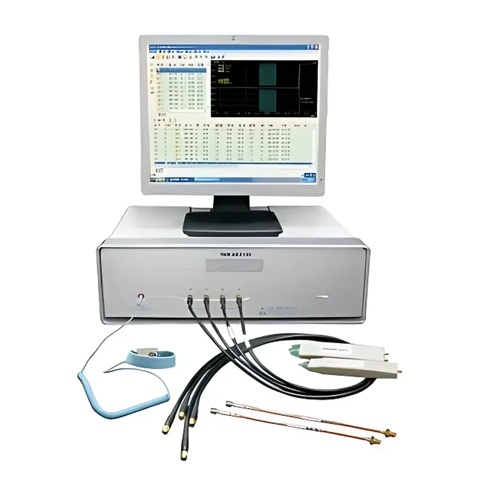
Aisida TDR-ZK2130 Time-Domain Reflectometry Characteristic Impedance Analyzer
| Brand | Aisida |
|---|---|
| Model | TDR-ZK2130 |
| Origin | Guangdong, China |
| Measurement Principle | Time-Domain Reflectometry (TDR) |
| Impedance Range (Single-Ended) | 10–150 Ω |
| Impedance Range (Differential) | 20–300 Ω |
| Accuracy (at 50 Ω) | ±1% |
| Repeatability (at 50 Ω) | ±0.5% |
| Measurement Length | 0.04–2 m |
| Horizontal Resolution | 0.2 mm |
| Vertical Resolution | 0.03 Ω |
| TDR Bandwidth | >3 GHz |
| Sampling Oscilloscope Bandwidth | >5 GHz |
| Incident Pulse Rise Time | <80 ps |
| Time Sampling Resolution | 10 ps |
| Supported Modes | Single-ended, Differential, Common-mode impedance |
| Statistical Process Control (SPC) Module | Integrated |
| Channel Configurations | 2-channel or 4-channel operation |
| Compliance Standards | IEEE 1394a/b, DiiVA, DisplayPort, HDMI 1.4, SATA I/II, USB 2.0/3.0 |
Overview
The Aisida TDR-ZK2130 is a dedicated time-domain reflectometry (TDR) analyzer engineered for high-precision, repeatable characterization of transmission line impedance in printed circuit boards (PCBs), flexible circuits, coaxial cables, and high-speed data interconnects. Unlike general-purpose sampling oscilloscopes, the TDR-ZK2130 integrates hardware-optimized TDR pulse generation with application-specific firmware and calibration algorithms tailored to impedance validation workflows in electronics manufacturing. It operates on the fundamental principle that an incident step signal reflects proportionally to local impedance discontinuities along a transmission path; by analyzing the amplitude and timing of reflected waveforms, the instrument calculates point-wise characteristic impedance with sub-millimeter spatial resolution. Designed for integration into R&D labs, design verification centers, and production QA lines, the system delivers traceable, standards-aligned measurements without requiring manual waveform interpretation or external post-processing.
Key Features
- Automated, batch-capable impedance testing with configurable pass/fail thresholds and multi-site measurement sequencing
- Dual operating modes: single-ended (10–150 Ω) and differential (20–300 Ω), including common-mode impedance and skew analysis (intra-pair, inter-pair, differential delay)
- Scalable channel architecture supporting 2-channel or 4-channel simultaneous acquisition for parallel cable or PCB trace evaluation
- High-fidelity TDR subsystem with >3 GHz effective bandwidth, <80 ps incident rise time, and 10 ps time sampling resolution
- Integrated Windows-based software with intuitive GUI, embedded test file editor, and one-click report generation
- Comprehensive data management: automatic timestamped storage of raw waveforms, impedance profiles, statistical summaries, and SPC-compliant control charts
- Direct thermal or laser printing support for test reports, impedance plots, and pass/fail summaries compliant with internal audit requirements
Sample Compatibility & Compliance
The TDR-ZK2130 is validated for use across rigid FR-4, polyimide flex, and high-frequency laminates (e.g., Rogers RO4000®, Isola I-Tera®), as well as coaxial, twisted-pair, and ribbon cables used in consumer electronics, automotive infotainment, and industrial communication systems. Its measurement methodology aligns with industry-standard impedance validation practices referenced in IPC-TM-650 Method 2.5.5.7 (TDR-based impedance measurement), ASTM D257 (surface resistivity), and IEC 61188-5-2 (PCB impedance specification). The instrument supports full compliance verification against high-speed interface specifications—including HDMI 1.4, DisplayPort 1.4, USB 3.0 SuperSpeed, SATA III, and IEEE 1394b—by enabling user-defined impedance windowing, length-dependent tolerance mapping, and differential pair balance assessment per JEDEC JESD22-B111 and PCI-SIG compliance guidelines.
Software & Data Management
The embedded Windows application provides full lifecycle test management: from parameterized test plan creation (via drag-and-drop template editor) to automated execution, real-time waveform overlay, and statistical analysis. All raw TDR waveforms are stored in vendor-neutral binary format with metadata (date/time, operator ID, fixture calibration ID, environmental conditions). The integrated SPC module computes Cp/Cpk, X-bar & R charts, histogram distributions, and outlier detection per ISO 22514-2. Audit-ready data export supports CSV, XML, and PDF formats; optional configuration enables 21 CFR Part 11-compliant electronic signatures, user access tiers, and immutable audit trails for GLP/GMP-regulated environments. No third-party licenses or runtime dependencies are required.
Applications
Typical deployment scenarios include: impedance validation of high-density HDI PCB stack-ups during design sign-off; incoming material inspection of RF coaxial cables and LVDS flex assemblies; in-line impedance monitoring during solder mask or plating process qualification; failure analysis of signal integrity anomalies in high-speed SerDes channels; and supplier certification testing for automotive Ethernet (100BASE-T1, 1000BASE-T1) and PCIe Gen4/Gen5 interconnects. The system is routinely employed by Tier-1 PCB fabricators, cable OEMs, and contract manufacturers to meet IPC-A-600G acceptability criteria and customer-specific PPAP documentation requirements.
FAQ
What calibration standards does the TDR-ZK2130 support?
The instrument includes factory-traceable calibration using NIST-traceable open/short/load standards and supports user-performed two-port calibration via SOLT (Short-Open-Load-Thru) or TRL (Thru-Reflect-Line) methods for fixture de-embedding.
Can the system integrate with MES or factory automation platforms?
Yes—via TCP/IP socket interface and Modbus TCP protocol, enabling bidirectional communication with SCADA, MES, and PLC systems for automated job dispatch and result ingestion.
Is differential impedance measurement performed using true differential TDR or derived calculation?
The TDR-ZK2130 implements true differential TDR stimulation using independently controlled, phase-matched step sources, ensuring accurate modeling of coupled-mode propagation without mathematical approximation.
Does the software support custom report templates compliant with internal QA documentation standards?
Yes—the report generator includes a WYSIWYG template editor supporting company logos, header/footer fields, dynamic field insertion (e.g., lot number, revision ID), and conditional formatting based on measurement outcomes.
What is the recommended recalibration interval under continuous production use?
Aisida recommends annual recalibration verified against certified reference standards; however, daily verification using built-in reference traces and drift-compensated baseline correction ensures measurement stability between formal calibrations.


