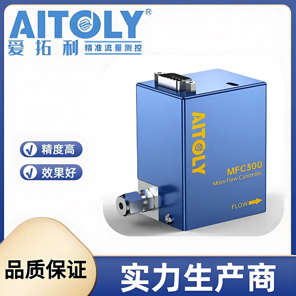
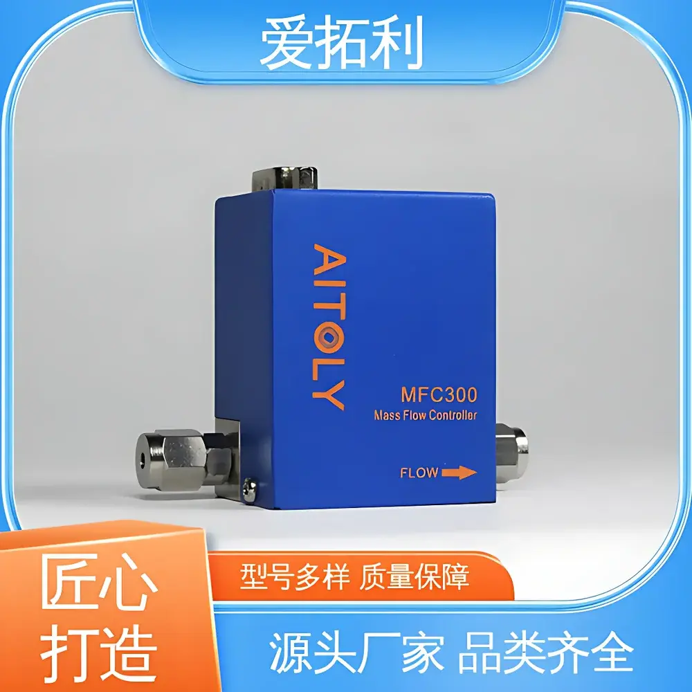
AITOLY MFC300 Thermal Mass Flow Controller
| Brand | AITOLY |
|---|---|
| Model | MFC300 |
| Type | Thermal Mass Flow Controller |
| Flow Range | 0–5 / 10 / 50 / 100 / 200 / 300 / 500 SCCM |
| Accuracy | ±0.5% F.S. |
| Linearity | ±1% F.S. |
| Repeatability | ±0.5% F.S. |
| Response Time | <1 s |
| Operating Pressure Drop | 0–1 MPa |
| Ambient Temperature | 0–65 °C |
| Power Supply | 15–40 VDC |
| Output Interfaces | Analog (0–5 V / 4–20 mA), RS232, RS485, RS422, CAN (galvanically isolated) |
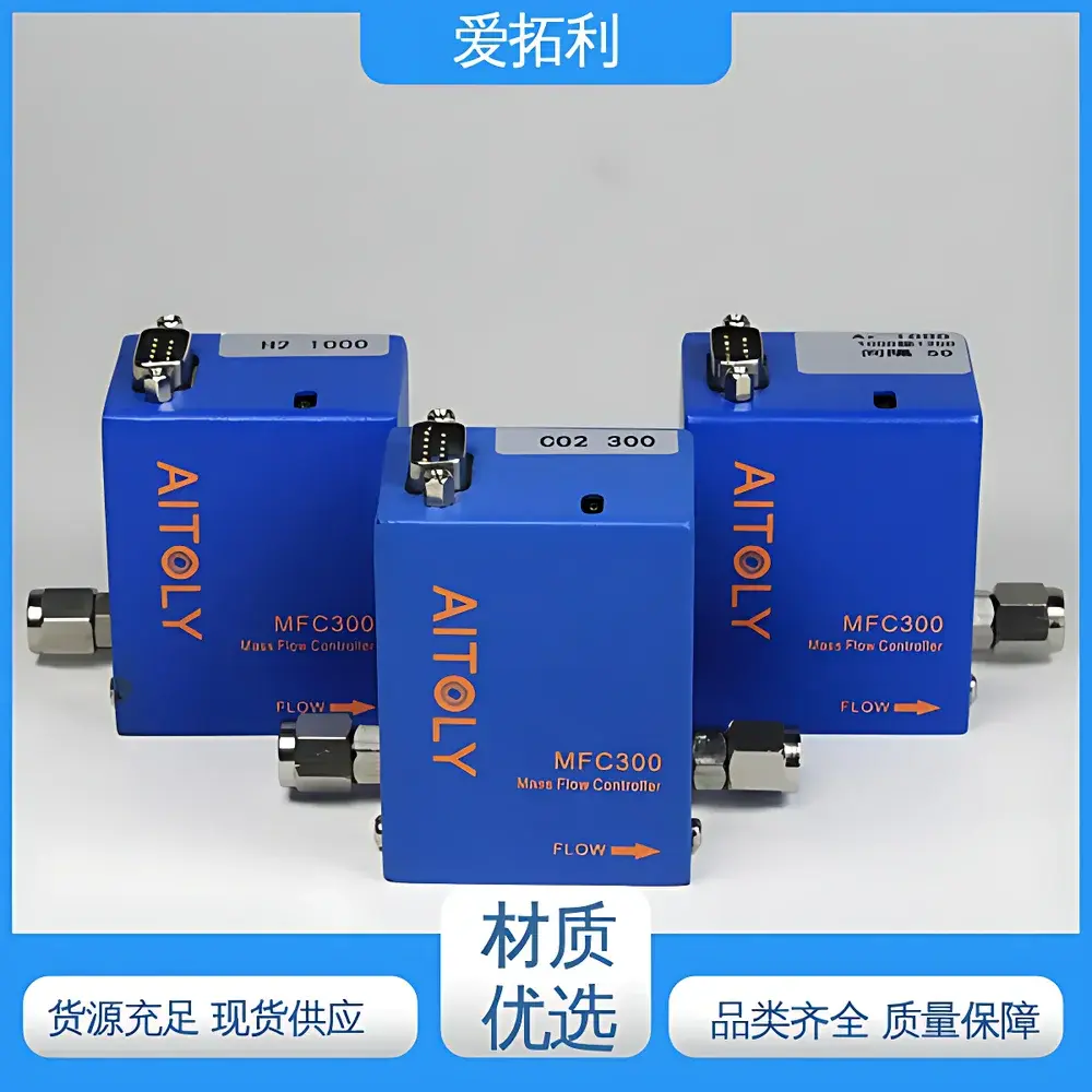
| Gas Compatibility | Air, Ar, N₂, O₂, CO₂, CH₄ |
| Gas Path Connection | 3–3.2 mm, 4 mm, or 6 mm tubing |
| Standard Fittings | M8×1, 4 mm push-to-connect, 6 mm push-to-connect |
| Housing Dimensions (L×W×H) | 62.5 × 40 × 62.5 mm (base variant), 51 × 39.9 × 73 mm (compact variant) |
| Zero Drift | Extremely low |
| Moving Parts | None |
Overview
The AITOLY MFC300 is a high-stability thermal mass flow controller engineered for precise, real-time regulation and measurement of gas flow rates in industrial process control, laboratory instrumentation, and analytical systems. Based on constant-temperature anemometry (CTA), the device measures mass flow directly—without dependence on pressure or temperature compensation—by detecting heat transfer between a heated sensor element and the flowing gas stream. This principle enables true mass flow output in standardized cubic centimeters per minute (SCCM) or liters per minute (L/min), traceable to NIST-traceable calibration standards. The MFC300 operates across a wide dynamic range—from ultra-low flows (0–5 SCCM) to medium-range flows (up to 5 L/min)—with no moving parts, eliminating mechanical wear and ensuring long-term reliability under continuous operation. Its compact monolithic housing, combined with galvanically isolated digital interfaces and dual analog outputs, supports seamless integration into automated gas delivery subsystems compliant with ISO/IEC 17025 and ASTM D7213 (for gas flowmeter calibration).
Key Features
- Thermal mass flow sensing architecture with zero moving components—ensures maintenance-free operation and immunity to particulate-induced clogging
- Multi-gas capability with pre-configured calibration curves for Air, Ar, N₂, O₂, CO₂, and CH₄; user-selectable gas type via digital interface
- High metrological performance: ±0.5% full-scale (F.S.) accuracy, ±0.5% F.S. repeatability, and <1 second response time (10–90% step change)
- Extremely low zero drift (<0.05% F.S./°C), validated over 0–65 °C ambient operating range
- Flexible power and signal architecture: single 15–40 VDC supply; simultaneous analog (0–5 V / 4–20 mA) and digital outputs (RS232, RS485, RS422, CAN bus with galvanic isolation)
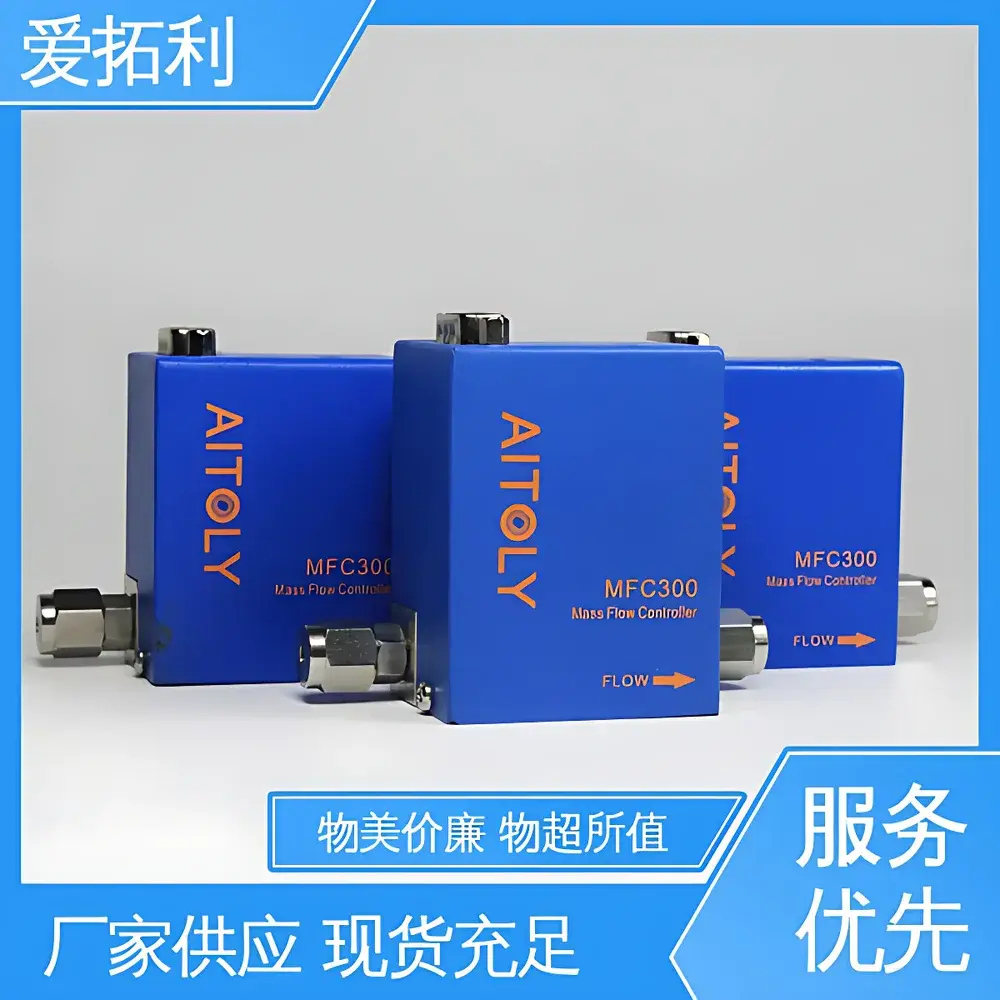
- Modular mechanical design supporting multiple tubing diameters (3–3.2 mm, 4 mm, 6 mm) and industry-standard fittings (M8×1 metric thread, push-to-connect for 4 mm and 6 mm OD tubing)
Sample Compatibility & Compliance
The MFC300 is qualified for use with non-corrosive, non-condensing, particle-free gases at pressures up to 1 MPa differential. It meets IEC 61000-6-2 (immunity) and IEC 61000-6-4 (emissions) for industrial electromagnetic compatibility. While not intrinsically safe certified, it complies with CE marking requirements for EMC and RoHS 2011/65/EU. For regulated environments—including pharmaceutical cleanrooms (ISO 14644), semiconductor fab gas cabinets, or GLP-compliant QC labs—the device supports audit-ready configuration logging and firmware versioning when paired with the optional MCL300 master controller. All factory calibrations are performed per ISO/IEC 17025-accredited procedures, with certificate-of-calibration documentation available upon request.
Software & Data Management
The MFC300 supports bidirectional communication via ASCII-based command protocols over all digital interfaces. Configuration parameters—including setpoint ramp rate, gas selection, analog scaling, and alarm thresholds—are programmable without hardware modification. When connected to a host PC via USB-to-serial adapter or CAN interface, users can deploy AITOLY’s open-protocol SDK (C/C++, Python, LabVIEW drivers included) for custom SCADA integration. Firmware updates are delivered via secure binary flash over CAN or RS485. Audit trail functionality—including timestamped parameter changes and error logs—is retained in non-volatile memory and accessible through serial query commands, satisfying basic FDA 21 CFR Part 11 data integrity expectations for non-GMP research use.
Applications
- Precise gas dosing in CVD, PECVD, and ALD semiconductor thin-film deposition tools
- Carrier and purge gas control in GC, GC-MS, and ICP-MS analytical instrumentation
- Process gas blending and ratio control in hydrogen fuel cell test benches and electrolyzer R&D systems
- Leak testing and pressure decay validation in automotive EV battery module sealing lines
- Environmental chamber gas injection for controlled atmosphere aging studies (ASTM G151, ISO 4892)
- Calibration transfer standards for secondary flowmeters in metrology labs
FAQ
Does the MFC300 require external temperature or pressure compensation?
No. As a thermal mass flow controller, it outputs true mass flow (SCCM or SLPM) independent of upstream temperature and pressure fluctuations—provided operating conditions remain within specified limits (0–1 MPa ΔP, 0–65 °C ambient).
Can the device be calibrated for gases not listed in the standard set?
Yes. Custom calibration for additional gases (e.g., He, H₂, SF₆) is available as a factory service; calibration coefficients are stored in non-volatile memory and selected via digital command.
Is the CAN interface compatible with SAE J1939 or CANopen protocols?
The MFC300 implements a proprietary ASCII-over-CAN protocol optimized for deterministic flow control. It does not natively support J1939 or CANopen but can be interfaced via protocol translation gateways.
What is the recommended maintenance interval?
No scheduled maintenance is required. Periodic verification against a traceable reference standard is advised annually for critical applications per ISO/IEC 17025 clause 7.7.
How is zero calibration performed in-field?
Zero calibration is executed via digital command (‘ZCAL’) while gas flow is stopped and inlet/outlet valves are closed. The procedure takes <2 seconds and corrects for thermal drift without requiring physical adjustment.