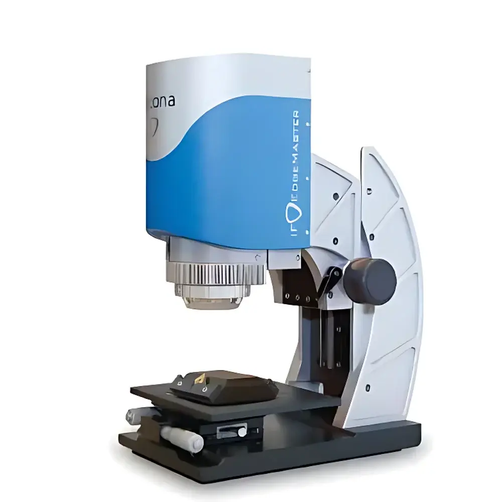
Alicona IF-EdgeMaster 3D Optical Tool Measurement System
| Brand | Alicona |
|---|---|
| Origin | Austria |
| Manufacturer Type | Authorized Distributor |
| Origin Category | Imported |
| Model | IF-EdgeMaster |
| Price Range | USD 68,000 – 109,000 |
| X/Y Travel Range | 25 mm × 25 mm |
| Z Travel Range | 130 mm (26 mm motorized) |
| Light Source | 24-segment LED ring light |
| Best Vertical Resolution | 20 nm |
| Minimum Measurable Radius | 2 µm |
| Minimum Measurable Wedge Angle | 20° |
| Minimum Measurable Roughness (Ra) | 80 nm |
| Minimum Measurable Areal Roughness (Sa) | 50 nm |
| Maximum Chamfer Length | 4000 µm |
| Maximum Tilt Angle | 87° |
| Surface Structure Requirement | Ra > 9 nm, Lc = 2 µm |
| Max Sample Height | 155 mm |
| Max Sample Weight | 4 kg |
Overview
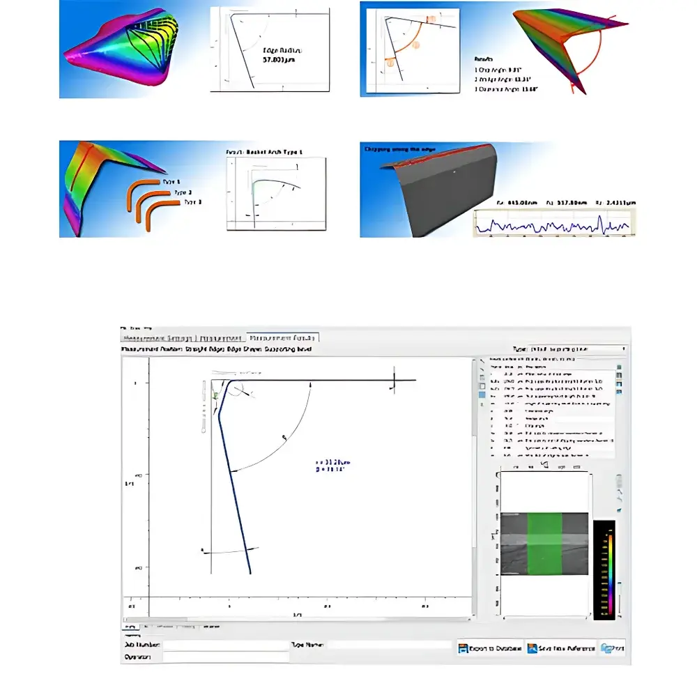
The Alicona IF-EdgeMaster is a fully automated 3D optical tool measurement system engineered specifically for high-precision metrology of cutting tools in production and R&D environments. It employs Focus-Variation technology—a robust optical principle combining high-numerical-aperture microscopy with precise vertical scanning—to simultaneously capture topography, edge geometry, and surface texture across complex, steep, and multi-material tool surfaces. Unlike conventional contact profilometers or standard confocal systems, Focus-Variation delivers sub-micron lateral resolution and nanometric vertical repeatability without requiring sample coating or vacuum conditions. Its core strength lies in the ability to measure both macro-geometric features—such as rake angle, clearance angle, wedge angle, and chamfer dimensions—and micro-scale attributes—including edge radius (rβ), edge rounding (Kab), flank wear volume, and areal roughness (Sa, Sq) within a single, unbroken acquisition sequence. Designed for integration into ISO/IEC 17025-compliant calibration labs and aerospace-grade manufacturing cells, the IF-EdgeMaster supports traceable, auditable measurements aligned with DIN EN ISO 25178-2 and VDI/VDE 2634 Part 3 standards.
Key Features
- Fully automated measurement workflow—from part loading to report generation—reducing operator dependency and enabling consistent inter-shift reproducibility.
- Motorized Z-axis with 26 mm active travel and 20 nm vertical resolution ensures stable focus tracking across steep flanks (up to 87° tilt) and deep grooves.
- 24-segment programmable LED ring light enables dynamic illumination optimization per surface orientation, minimizing shadowing on helical flutes and serrated edges.
- Integrated high-precision XYZ stage (25 mm × 25 mm × 130 mm) with thermal drift compensation maintains geometric fidelity during extended measurement cycles.
- Non-contact operation eliminates mechanical wear on delicate coatings (e.g., TiAlN, DLC) and preserves edge integrity during repeated inspections.
- Real-time edge detection algorithm automatically identifies and segments cutting edges, chamfers, and groove boundaries prior to quantitative analysis.
Sample Compatibility & Compliance
The IF-EdgeMaster accommodates rotating and static cutting tools up to 155 mm in height and 4 kg in mass—including end mills, drills, inserts, reamers, and broaches—with no size-dependent recalibration required. Its optical architecture supports measurement of surfaces with Ra ≥ 9 nm and autocorrelation length (Lc) ≥ 2 µm, making it suitable for ground, polished, PVD/CVD-coated, and laser-textured tool surfaces. All measurement routines comply with GLP and GMP documentation requirements, including full audit trails, electronic signatures (per FDA 21 CFR Part 11), and calibration certificate traceability to national metrology institutes (e.g., PTB, NIST). The system meets essential safety and EMC directives under CE marking (2014/30/EU, 2014/35/EU) and conforms to ISO 10360-5 for coordinate measuring machine performance verification.
Software & Data Management
Controlled via Alicona’s proprietary MeasureSoft platform, the IF-EdgeMaster provides an intuitive, role-based interface with customizable measurement templates, batch processing queues, and automated pass/fail decision logic based on user-defined GD&T tolerances. Raw point-cloud data (STL, OBJ, CSV) and calibrated height maps (TIFF, PNG) are stored with embedded metadata—including instrument ID, environmental logs, calibration status, and operator credentials. Export modules support direct integration with MES (e.g., Siemens Opcenter) and PLM systems (e.g., Teamcenter), while PDF reports include annotated cross-sections, 3D deviation maps, statistical summaries (Cp/Cpk), and comparison overlays against CAD nominal models. Data retention policies adhere to ISO 9001:2015 clause 7.5.3, supporting long-term trend analysis and SPC implementation.
Applications
- Quantitative validation of edge preparation processes (e.g., vibratory finishing, electropolishing, plasma treatment) through repeatable rβ and Kab assessment.
- Wear progression monitoring in cutting tool life studies, including flank wear volume calculation, crater depth mapping, and notch formation quantification.
- Verification of micro-geometric tolerances for aerospace turbine blade milling cutters and medical bone-saw inserts under AS9100 and ISO 13485 frameworks.
- Root cause analysis of premature tool failure by correlating local roughness anomalies (Sa < 50 nm) with machining-induced micro-cracking or coating delamination.
- Process capability studies for high-feed milling tools where chamfer width consistency (±0.5 µm) directly impacts surface finish stability and burr formation.
FAQ
Does the IF-EdgeMaster require sample coating or conductive preparation before measurement?
No. As a non-contact optical system, it measures bare metallic, ceramic, and coated tool surfaces without sputtering, carbon coating, or vacuum chamber use.
Can it measure tools with helical geometries or internal coolant channels?
Yes. Multi-angle focus stacking and automatic tilt compensation enable full 3D reconstruction of fluted end mills and drill bits with pitch angles up to 45°.
Is calibration traceable to international standards?
Yes. Alicona provides factory calibration certificates traceable to PTB (Germany) and includes on-site verification using certified step-height and roughness artifacts per ISO 25178-60.
What file formats does it export for downstream CAE or CAM integration?
Standard exports include ISO-standard STEP AP214 geometry files, GD&T-annotated PDF reports, and ASCII point clouds compatible with PolyWorks, Metrolog X4, and VERICUT toolpath simulation.
How is measurement uncertainty determined for edge radius results?
Uncertainty budgets follow JCGM 100:2008 guidelines and incorporate contributions from focus noise, stage positioning error, edge detection algorithm repeatability, and reference artifact calibration uncertainty—typically U = ±(15 nm + 0.5% of measured rβ) at k=2.