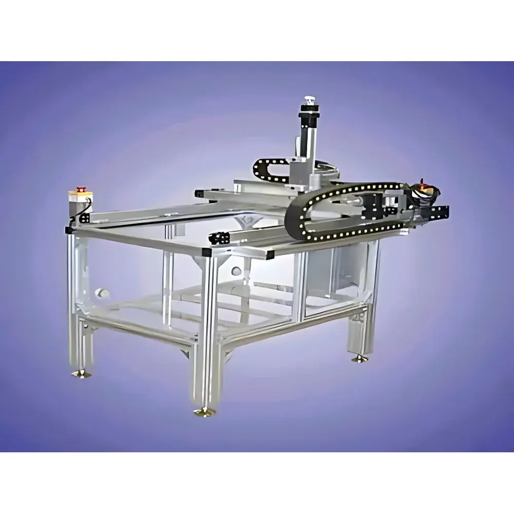
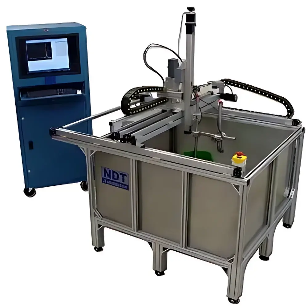
Analysis UPK-T24 Immersion Ultrasonic C-Scan System
| Brand | Analysis |
|---|---|
| Origin | USA |
| Model | UPK-T24 |
| Scanning Range | 600 × 450 × 300 mm |
| Gain Range | 0–110 dB |
| Vertical Linearity | ≤2% |
| Horizontal Linearity | ≤2% |
| Dynamic Range | ≥95 dB |
| Inspection Method | Pulse-Echo |
| Waveform Type | Pulsed Ultrasonic |
| Transducer Configuration | Single-Crystal or Through-Transmission |
Overview
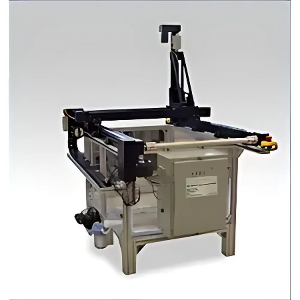
The Analysis UPK-T24 Immersion Ultrasonic C-Scan System is a precision-engineered, computer-controlled ultrasonic non-destructive testing (NDT) platform designed for high-resolution volumetric imaging of internal discontinuities in advanced materials. Operating on the pulse-echo principle—where short-duration ultrasonic bursts are transmitted into a water-coupled specimen and reflected echoes are time-gated and amplitude-analyzed—the system generates quantitative C-scan maps representing reflectivity at selected depth gates. Unlike manual contact scanning, immersion-based coupling ensures consistent acoustic impedance matching, eliminates operator-induced variability, and enables repeatable, automated raster or contour-following inspections. The UPK-T24 is purpose-built for applications demanding metrological traceability and regulatory compliance, including aerospace structural integrity verification, composite material qualification per ASTM E2700 and MIL-STD-271, and high-value component acceptance testing in defense and energy sectors.
Key Features
- Modular, PCI Express–based ultrasonic acquisition architecture with up to 30 MHz analog bandwidth and 12-bit digitization resolution, supporting high-fidelity echo capture and precise time-of-flight (TOF) measurement.
- Multi-axis motion control system (4–8 axes configurable) integrated with high-resolution optical encoders, enabling programmable scan trajectories—including planar raster, cylindrical unwrapping, and freeform surface following—with positional repeatability of ±0.025 mm and maximum traverse speed of 500 mm/s.
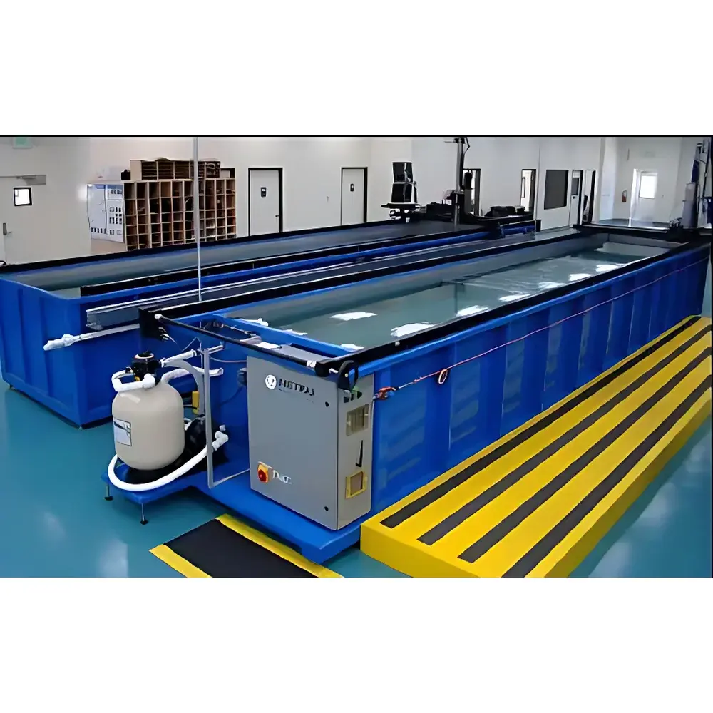
- Robust immersion tank or gantry-mounted scanning frame engineered for stable operation across temperature-controlled water baths (optional chiller integration), minimizing thermal drift during extended inspection cycles.
- Dual transducer support: compatible with focused single-crystal probes (5–25 MHz) for high-resolution near-surface defect detection, as well as through-transmission configurations using separate transmitter/receiver pairs for attenuation-based volumetric assessment.
- Real-time A-scan buffering, B-scan slicing, and C-scan image reconstruction with adjustable gate width, thresholding, and color-mapped amplitude scaling—all processed onboard without host CPU dependency.
Sample Compatibility & Compliance
The UPK-T24 accommodates flat, curved, and rotationally symmetric components up to 600 mm × 450 mm in footprint and 300 mm in immersion depth. It is routinely deployed for inspection of carbon-fiber-reinforced polymer (CFRP) laminates, aluminum honeycomb cores, titanium alloy forgings, ceramic matrix composites (CMCs), and additive-manufactured metal parts. System design adheres to ISO 16810:2014 (Ultrasonic Testing — General Principles), ASTM E1316 (Standard Terminology for Nondestructive Examinations), and supports audit-ready documentation required under AS9100 Rev D and FAA AC 20-108B. Optional software modules provide full traceability per FDA 21 CFR Part 11 for electronic signatures, secure user roles, and immutable audit trails—enabling deployment in GLP/GMP-regulated environments.
Software & Data Management
The system runs on a dedicated Windows-based application suite featuring intuitive graphical workflow configuration, real-time image rendering, and multi-layer data annotation. Core capabilities include automatic flaw sizing per ASTM E2373, thickness mapping via back-wall echo analysis, and statistical process control (SPC) chart generation for production-line monitoring. All raw RF data, position logs, and processed images are stored in vendor-neutral HDF5 format, ensuring long-term archival integrity and third-party interoperability. Batch report generation supports customizable templates compliant with NADCAP AC7114/1 and customer-specific quality records. Remote diagnostics and firmware updates are supported via encrypted TLS channels—no external internet exposure required.
Applications
- Aerospace: Detection and quantification of disbonds, porosity, delamination, and foreign object debris (FOD) in wing skins, fuselage panels, and engine nacelle structures.
- Defense: Certification of armor-grade composites, missile body integrity verification, and ordnance casing inspection per MIL-STD-2132.
- Energy: Assessment of wind turbine blade root joints, nuclear fuel cladding integrity screening, and weld inspection in pressure vessel liners.
- R&D Laboratories: Material property correlation studies (e.g., void fraction vs. ultrasonic attenuation), process parameter optimization for automated fiber placement (AFP), and validation of simulation models (e.g., CIVA, PZFlex).
- Manufacturing QA: In-line inspection of CFRP prepreg layups, post-cure evaluation of autoclave-bonded assemblies, and final acceptance testing prior to shipment.
FAQ
What standards does the UPK-T24 comply with for aerospace NDT?
The system meets requirements outlined in ASTM E2700 (Standard Practice for Ultrasonic Testing of Flat Panel Composites), MIL-STD-271 (Ultrasonic Inspection of Metals), and supports procedural qualification per NAS 410 and EN 4179.
Can the system perform through-transmission and pulse-echo modes simultaneously?
Yes—dual-channel configurations allow concurrent acquisition from separate transmitter and receiver transducers, enabling comparative attenuation analysis alongside reflection-based C-scan mapping.
Is the software validated for regulated industries?
Optional IQ/OQ/PQ documentation packages and 21 CFR Part 11-compliant audit trail functionality are available for pharmaceutical, medical device, and nuclear applications.
What is the minimum detectable flaw size in CFRP using standard 10 MHz focused probes?
Under optimal coupling and signal-to-noise conditions, planar defects ≥0.2 mm in lateral dimension and ≥0.05 mm in through-thickness extent are reliably resolved in 6-mm-thick quasi-isotropic CFRP laminates.
Does the system support custom motion profiles for complex geometries?
Yes—via integrated CAD import (STEP/IGES), the software computes adaptive toolpaths for contoured surfaces, including variable standoff distance control and dynamic focus tracking.


")
