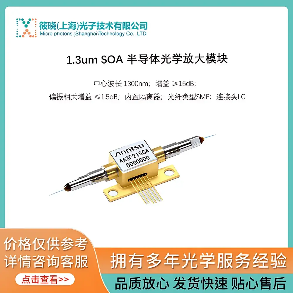
Anritsu SOA-W1300-G15-SL 1.3 µm Semiconductor Optical Amplifier Module
| Brand | Anritsu |
|---|---|
| Origin | Japan |
| Model | SOA-W1300-G15-SL |
| Wavelength | 1300 nm |
| Operating Band | O-band (1260–1360 nm) |
| Gain | ≥15 dB |
| Polarization-Dependent Gain (PDG) | <0.5 dB |
| Noise Figure | ≤7.5 dB |
| Input/Output Connector | FC/APC or FC/PC (configurable) |
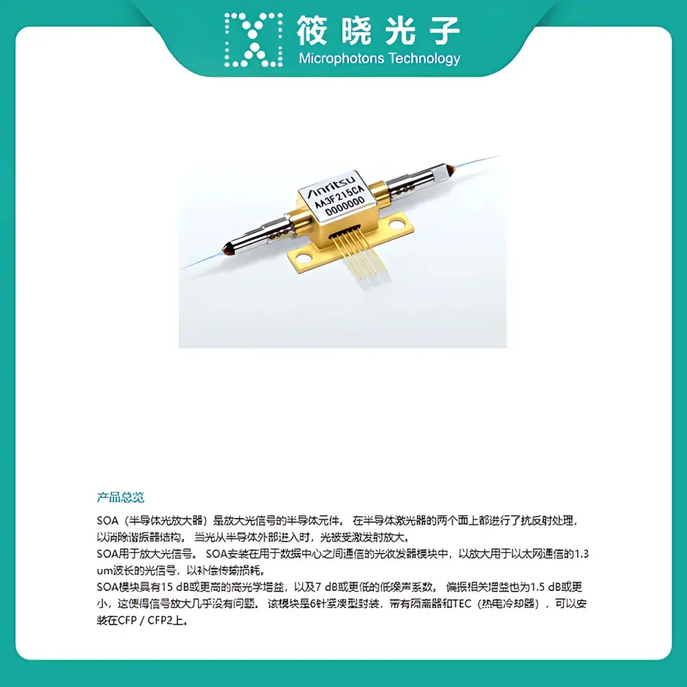
| Package Type | Butterfly 14-pin with TEC and Monitor Photodiode |
| Operating Temperature | 15–35 °C |
| Compliance | RoHS, CE, Telcordia GR-468-CORE |
Overview
The Anritsu SOA-W1300-G15-SL is a high-stability, gain-saturated semiconductor optical amplifier (SOA) module engineered for precision amplification in the O-band (1260–1360 nm), with a nominal operating wavelength of 1300 nm. Unlike erbium-doped fiber amplifiers (EDFAs), which dominate the C- and L-bands, this SOA leverages quantum-well active waveguide technology to deliver fast gain dynamics, compact footprint, and polarization-insensitive operation—making it ideal for time-resolved optical signal processing, wavelength conversion, optical switching, and low-latency photonic integrated circuit (PIC) test environments. Its monolithic InP-based structure ensures high coupling efficiency with standard single-mode fiber (SMF-28), while integrated thermoelectric cooling (TEC) and monitor photodiode enable closed-loop bias and temperature stabilization—critical for maintaining consistent small-signal gain and noise figure across laboratory and manufacturing test benches.
Key Features
- Optimized for the O-band: Designed specifically for 1300 nm window applications including legacy PON systems, optical time-domain reflectometry (OTDR), and silicon photonics characterization.
- High gain & low noise: Delivers ≥15 dB small-signal gain with a noise figure ≤7.5 dB—enabling sensitive detection without cascaded amplifier penalty.
- Polarization-insensitive architecture: Polarization-dependent gain (PDG) <0.5 dB ensures stable performance under arbitrary input polarization states—essential for uncontrolled lab environments.
- Integrated thermal and optical monitoring: Built-in TEC controller interface and rear-facet monitor photodiode support real-time bias current and temperature feedback for long-term drift compensation.
- Hermetically sealed butterfly package: 14-pin configuration includes dedicated pins for TEC drive, monitor PD, and anode/cathode contacts—facilitating seamless integration into automated test equipment (ATE) racks and optical alignment stations.
- RoHS-compliant and Telcordia GR-468-CORE qualified: Validated for reliability under thermal cycling, mechanical shock, and humidity exposure—meeting industrial-grade deployment requirements.
Sample Compatibility & Compliance
The SOA-W1300-G15-SL is compatible with standard SMF-28 and HI1060 fibers via FC/APC or FC/PC connectors (user-selectable at order). It supports both continuous-wave (CW) and modulated input signals up to 10 Gb/s without gain saturation artifacts, provided input power remains within –30 to –10 dBm range. The module complies with IEC 61300-2 series for fiber optic device testing, adheres to ISO 9001-certified manufacturing protocols at Anritsu’s Yokohama facility, and meets EU Directive 2011/65/EU (RoHS 2) and 2014/30/EU (EMC). For regulated environments—including GLP-compliant optical component validation labs—it supports traceable calibration documentation upon request (per ISO/IEC 17025 guidelines).
Software & Data Management
While the SOA-W1300-G15-SL operates as a stand-alone analog optical component, its electrical interfaces are fully compatible with industry-standard instrumentation control frameworks. Bias current and TEC voltage can be managed via analog voltage inputs (0–5 V) or digital I²C commands (address configurable), enabling synchronization with LabVIEW, Python (PyVISA), or MATLAB-based test automation suites. Optional firmware-enabled logging (via external microcontroller) supports timestamped gain tracking, thermal history, and fault-event capture—facilitating audit-ready data retention aligned with FDA 21 CFR Part 11 principles when deployed in regulated R&D workflows.
Applications
- Pre-amplification stage in 1310 nm OTDR receivers to improve dynamic range and spatial resolution.
- Gain medium in all-optical logic gates and Mach–Zehnder interferometer-based wavelength converters.
- Signal boost in multi-channel optical coherence tomography (OCT) systems requiring sub-microsecond gain recovery.
- Benchtop characterization of silicon nitride (SiN) and lithium niobate (LiNbO₃) modulators operating in the O-band.
- Low-cost alternative to EDFA in short-reach passive optical networks (PON) transceiver development and failure analysis.
FAQ
What is the maximum input power before gain compression occurs?
For linear operation, input power should not exceed –10 dBm; compression >1 dB begins at approximately –5 dBm under typical bias conditions.
Can this SOA be used in pulsed operation (e.g., with femtosecond lasers)?
Yes—its carrier lifetime (~100 ps) supports amplification of pulses down to ~10 ps duration, though group velocity dispersion must be compensated externally for transform-limited output.
Is factory calibration data provided with each unit?
Each module ships with a test report listing measured small-signal gain, noise figure, PDG, and spectral gain flatness across 1260–1360 nm—traceable to NMIJ (National Metrology Institute of Japan) reference standards.
Does the module support automatic power control (APC) mode?
No—APC requires external photodiode feedback loop integration; however, the integrated monitor PD enables user-implemented APC via PID-controlled current source.
What is the recommended warm-up time to achieve thermal stability?
Allow ≥15 minutes after power-on for TEC settling and gain stabilization; ambient temperature fluctuations >1 °C/min may extend stabilization time.


