AOE Tech PMFC Series Polarization-Maintaining Filter-Based 1×2 and 2×2 Fiber Couplers
| Brand | AOE Tech |
|---|---|
| Model | PMFC |
| Type | Polarization-Maintaining (PM) Filter-Based Coupler |
| Configuration | 1×2 / 2×2 |
| Operating Wavelengths | 1310 nm, 1550 nm, 980 nm, 1064 nm |
| Coupling Ratios | 1:99 to 50:50 (customizable) |
| Excess Loss | ≤0.7 dB (1×2, 1310/1550 nm) |
| Polarization Extinction Ratio (PER) | ≥20 dB (Type B), ≥22 dB (Type F) |
| Return Loss | ≥50 dB |
| Max Input Power | 300 mW |
| Fiber Type | Panda PM fiber (Ports 1 & 3) |
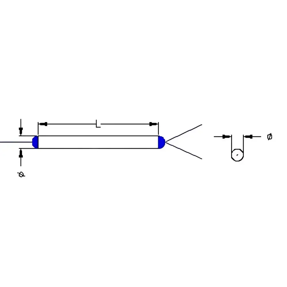
| Package Diameter × Length | φ5.5 mm × 35 mm |
| Operating Temperature | −5 °C to +70 °C |
| Storage Temperature | −40 °C to +80 °C |
| Connector Options | FC/APC, FC/UPC, SC/APC, SC/UPC |
| Slow-Axis Alignment | Key-aligned to connector key |
| Test Documentation | Full four-port IL, PER, and CR characterization per unit |
Overview
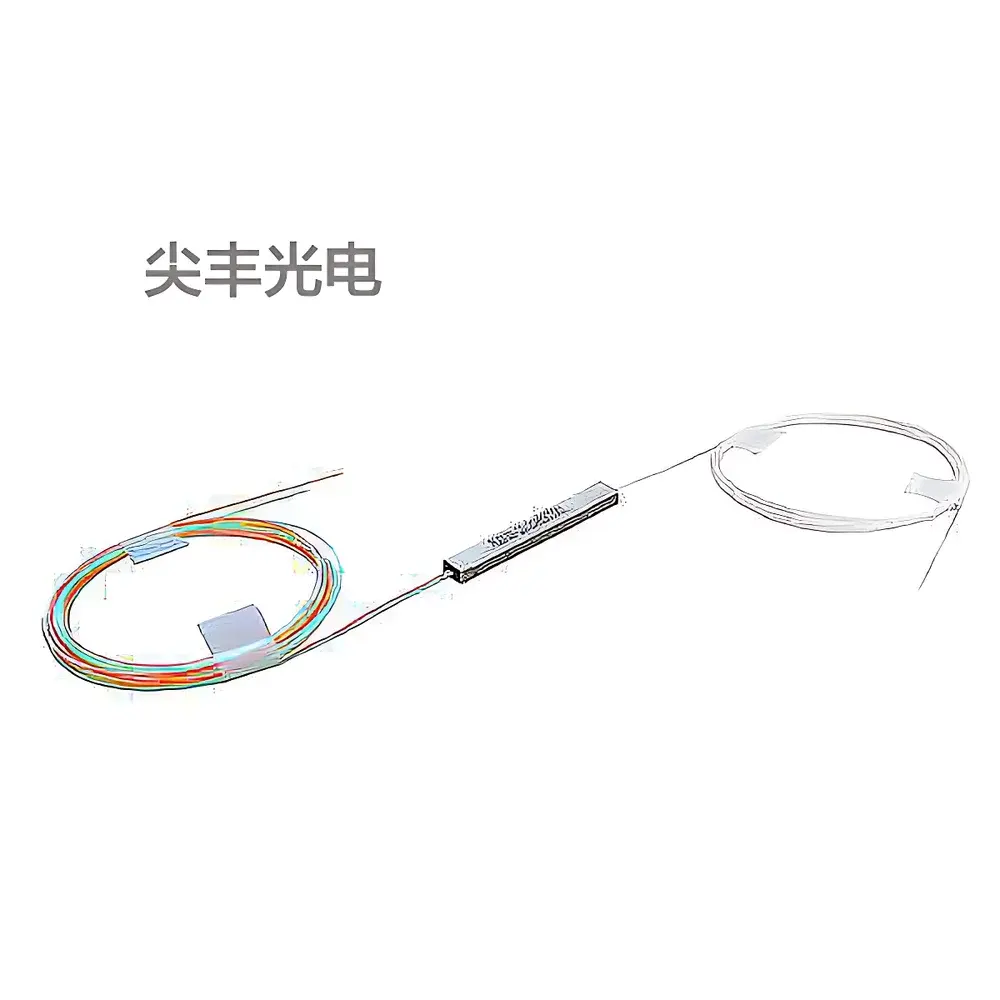
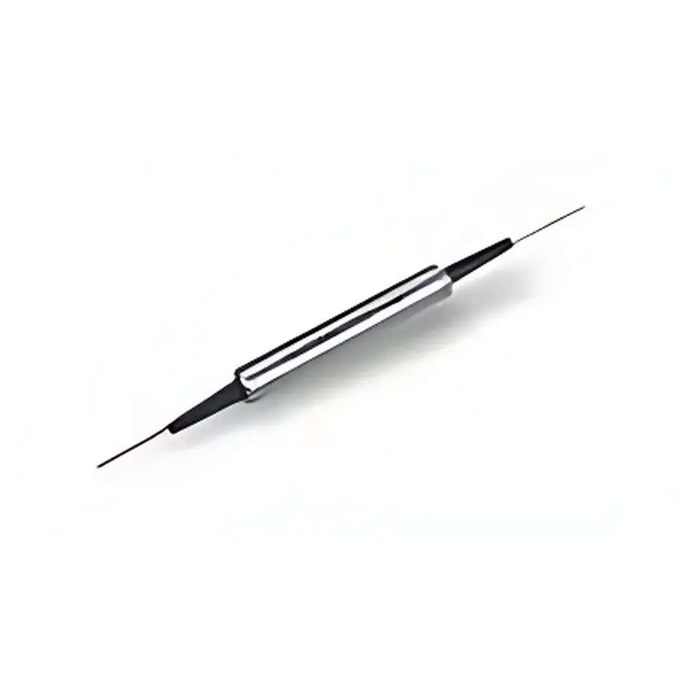
The AOE Tech PMFC Series Polarization-Maintaining Filter-Based Fiber Couplers are precision passive components engineered for stable, high-fidelity signal splitting and combining in polarization-sensitive photonic systems. Unlike fused biconical taper (FBT) or planar lightwave circuit (PLC) couplers, these devices employ thin-film interference filter technology integrated within a mechanically aligned, stress-engineered fiber assembly—ensuring minimal perturbation to the polarization state of guided light. Designed specifically for operation at standard telecom and industrial wavelengths (980 nm, 1064 nm, 1310 nm, and 1550 nm), each coupler is constructed using Panda-type polarization-maintaining fiber with precisely controlled birefringence. Critical to performance is the strict alignment of the slow axis of the PM fiber to the mechanical key of the connector (e.g., FC/APC), which must be maintained during system integration; functionality is only guaranteed when input light is launched along the designated slow axis. The compact cylindrical package (φ5.5 × 35 mm) accommodates space-constrained optical benches and embedded subsystems while preserving thermal and mechanical stability across laboratory and field-deployable environments.
Key Features
- Filter-based architecture ensures wavelength-selective coupling with low polarization-dependent loss (PDL) and high repeatability
- Panda PM fiber used in input and through ports (Ports 1 & 3); tap ports support SMF-28e, HI1060, or Panda fiber for flexible system integration
- High polarization extinction ratio (≥20 dB for Type B; ≥22 dB for Type F) verified per unit across all four port combinations
- Low excess loss (≤0.7 dB typical at 1310/1550 nm, 1×2 configuration) and tight uniformity (≤0.4 dB for 50:50 split)
- Hermetically sealed, epoxy-free assembly minimizes long-term drift and humidity-induced degradation
- Comprehensive factory test report included: insertion loss, extinction ratio, coupling ratio, and return loss for every operational port pair
- Connectorized interface with FC/APC standard (optional SC/APC, FC/UPC, SC/UPC) and key-aligned slow-axis orientation marking
Sample Compatibility & Compliance
The PMFC couplers are compatible with standard single-mode and polarization-maintaining fiber patch cables and are routinely deployed in systems requiring conformance with IEC 61300-2-4 (fiber optic interconnecting devices — tensile load test) and Telcordia GR-1209-CORE (reliability assurance for passive components). While not certified to ISO 9001 or FDA 21 CFR Part 11 by default, the manufacturing traceability, unit-level test data logging, and controlled cleanroom assembly process support integration into GLP- and GMP-compliant optical subsystems—including those used in medical laser delivery, aerospace-grade fiber-optic gyroscopes (FOGs), and quantum optics testbeds. The device’s maximum optical power handling (300 mW CW) meets Class 1M laser safety requirements under IEC 60825-1 when used with appropriate collimation and beam conditioning.
Software & Data Management
As a passive optical component, the PMFC coupler requires no firmware, driver software, or real-time control interface. However, its metrological integrity supports full traceability in automated test environments. Each unit ships with a calibration certificate listing measured values for insertion loss (IL), polarization extinction ratio (PER), coupling ratio (CR), and return loss (RL) at specified wavelengths—formatted in CSV-compatible ASCII for import into LabVIEW, Python (NumPy/Pandas), or MATLAB-based optical system modeling workflows. For production line integration, AOE Tech provides optional barcode-labeled packaging with unique serial identifiers, enabling ERP/MES linkage and audit-ready documentation per ISO/IEC 17025 guidelines.
Applications
- Fiber-optic gyroscopes (FOGs): as interferometric beam combiners/splitters maintaining coherence and polarization fidelity in Sagnac loop architectures
- EDFA and Raman amplifier monitoring: low-ratio taps (1%, 2%) for non-intrusive power sampling without disturbing gain dynamics
- Polarization-encoded quantum key distribution (QKD) systems: where preservation of Stokes vector orientation is critical for BB84 or E91 protocol fidelity
- Interferometric biosensors and distributed acoustic sensing (DAS): enabling common-path referencing with minimized polarization crosstalk
- Industrial laser material processing: beam sampling for closed-loop power stabilization in 1064 nm Nd:YAG or fiber laser systems
- Research-grade optical coherence tomography (OCT) engines: balanced detection paths requiring matched PER and IL across dual arms
FAQ
What happens if light is launched along the fast axis instead of the slow axis?
Performance degrades significantly: extinction ratio drops by >10 dB, coupling ratio becomes unstable, and excess loss increases unpredictably. These couplers are strictly slow-axis aligned and must be oriented accordingly during installation.
Can I use this coupler bidirectionally for both splitting and combining?
Yes—the device is intrinsically reciprocal. However, when used as a combiner, one output port must remain unterminated (or terminated with a 50 Ω optical load) to prevent back-reflection and interference effects that compromise extinction ratio.
Is the stated extinction ratio measured before or after connectorization?
All PER, IL, and CR values are measured on fully assembled units—including connectors—with slow-axis alignment verified optically using a rotating polarizer and power meter.
Do you offer custom coupling ratios outside the standard 1:99–50:50 range?
Yes. Custom ratios (e.g., 3:97, 7:93, 15:85) are available with lead times of 4–6 weeks and minimum order quantities of 10 units.
What is the impact of temperature cycling on polarization extinction ratio?
Within the specified operating range (−5 °C to +70 °C), PER variation is ≤0.8 dB over full cycle, validated per IEC 60068-2-14 (change of temperature).