API VEC Spatial Error Compensation System for Large-Scale CNC Machine Tools
| Origin | USA |
|---|---|
| Manufacturer Type | Authorized Distributor |
| Origin Category | Imported |
| Model | VEC |
| Price Range | USD $250,000 – $630,000 |
| Maximum Measurement Range | 160 m |
| Measurement Resolution | 0.08 µm |
| Spatial Accuracy | 10 µm + 5 µm/m |
| Horizontal Rotation | ±320° |
| Vertical Pitch | −59° to +79° |
| Roll Tilt | Unlimited |
Overview
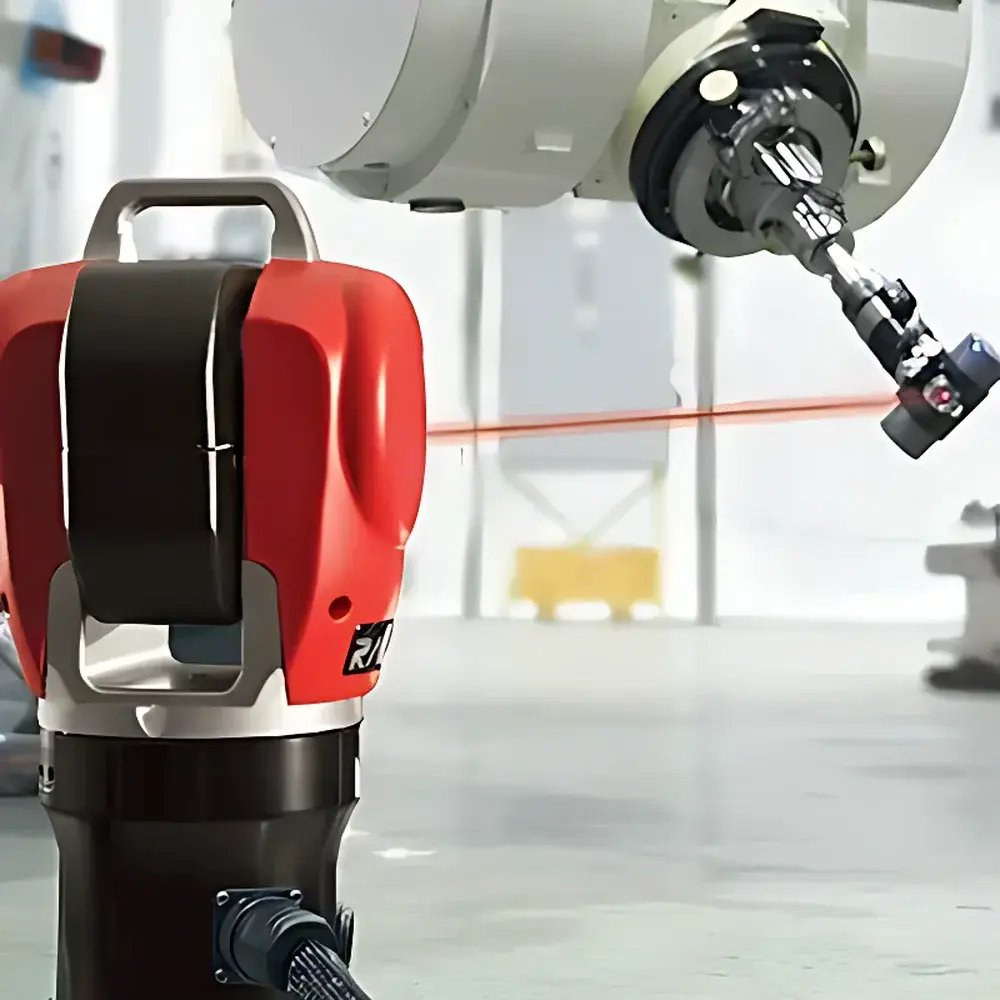
The API VEC (Vector-based Error Compensation) Spatial Error Compensation System is a metrology-grade solution engineered for rapid, high-fidelity volumetric calibration of large-scale multi-axis machine tools—including 5-axis and 6-axis CNC systems—using laser tracker–based kinematic modeling. Unlike conventional interferometric methods relying on sequential single-axis characterization, VEC employs a holistic, spatially continuous approach grounded in Chebyshev polynomial regression and rigid-body kinematics. It captures the full 6-degree-of-freedom (6-DOF) pose error field across the entire working volume by measuring hundreds of randomized reference points under real-world motion conditions. The system integrates API’s Radian laser tracker and motorized Active Target (AT), enabling uninterrupted beam lock during dynamic motion, even with complex toolpath trajectories and rotating axes. Designed for production-floor deployment, VEC reduces calibration time from days or weeks to 1–3 hours—minimizing thermal drift influence and machine downtime while delivering traceable, ISO 10360-compliant spatial accuracy of ≤10 µm + 5 µm/m.
Key Features
- Full volumetric error mapping via 200–400 randomized spatial sampling points, each measured with ≥30 repeated position captures for statistical robustness
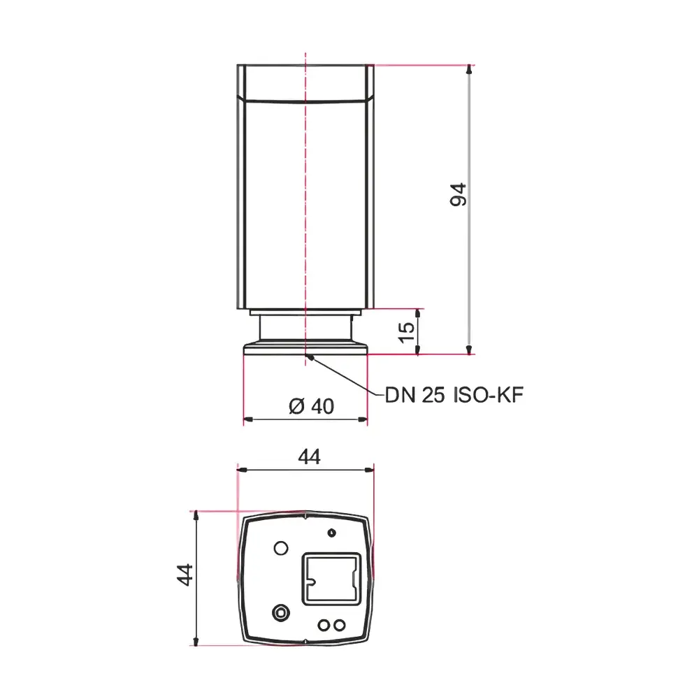
- Motorized Active Target with continuously rotating SMR ensures persistent laser lock during arbitrary 6-DOF motion—no beam dropouts or manual reacquisition required
- Adaptive path planning algorithm prevents mechanical collisions with fixtures, clamps, or structural obstructions using imported CAD geometry
- Triple-measurement protocol with variable-length AT mounting rods enables simultaneous acquisition of positional (X,Y,Z) and orientational (pitch, yaw, roll) error vectors
- Compact, portable Radian laser tracker supports both in-machine and external mounting configurations—optimized for shop-floor environmental stability
- Real-time feedback loop: measurement pauses at each point for 3–4 s to allow mechanical settling; tracker computes mean position before commanding next move
Sample Compatibility & Compliance
The VEC system is compatible with all major OEM large-format CNC platforms—including gantry mills, horizontal boring mills, and multi-axis machining centers—with or without rotary tables or tilting spindles. Its non-contact, line-of-sight methodology accommodates work envelopes up to 160 m in diameter. Calibration data conforms to ISO 230-2 (determining positioning accuracy) and ISO 230-6 (volumetric performance testing), supporting GLP/GMP documentation workflows. Measurement uncertainty budgets are fully traceable to NIST standards through API’s accredited calibration chain. The system supports audit-ready reporting per FDA 21 CFR Part 11 requirements when deployed with validated software configuration and electronic signature modules.
Software & Data Management
VEC operation is driven by API’s proprietary Metrology Software Suite, which includes model-driven path generation, real-time tracker synchronization, and automated error surface fitting using orthogonal Chebyshev polynomials. The software ingests native CAD models (STEP/IGES) to construct a parametric kinematic model of the machine’s axis architecture, then derives optimal measurement sequences that avoid singularities and collision zones. All raw tracker data—position, angle, timestamp, and environmental compensation values (temperature, pressure, humidity)—are logged in binary format with SHA-256 integrity hashing. Export options include CSV, XML, and native NC code formats for direct upload to Fanuc, Siemens, Heidenhain, and Mitsubishi CNC controllers. Audit trails record operator ID, session start/stop timestamps, software version, and parameter revision history—fully compliant with ISO 9001 and AS9100 quality management frameworks.
Applications
- Volumetric calibration of aerospace-grade 5-axis milling machines used in wing spar and engine casing fabrication
- Post-rebuild verification of large gantry-type coordinate measuring machines (CMMs) and inspection cells
- Production-line validation of additive manufacturing platforms with hybrid subtractive capabilities
- Thermal stability assessment of machine tools operating under ambient temperature gradients (e.g., unconditioned hangar environments)
- Pre-shipment certification for OEM machine tool deliveries requiring third-party metrological sign-off
- Periodic maintenance recalibration to maintain ASME B5.54 compliance over extended service intervals
FAQ
How does VEC differ from traditional laser interferometer-based calibration?
VEC measures the full 6-DOF error field simultaneously across the entire workspace using spatial sampling and kinematic modeling—whereas interferometers assess individual linear axes sequentially, requiring extensive setup, alignment, and thermal stabilization.
Is the Radian laser tracker required to be mounted on the machine itself?
No. The Radian can be positioned either on the machine structure or externally—its portability and wide angular range (±320° azimuth, −59° to +79° elevation) ensure full coverage without repositioning.
What level of training is required to operate the VEC system?
Operators require foundational knowledge of CNC kinematics and basic metrology principles. API provides certified Level II training (80-hour curriculum) covering measurement planning, model import, path validation, uncertainty analysis, and controller integration.
Can VEC compensate for geometric errors introduced by thermal expansion during operation?
VEC characterizes static geometric errors at stabilized ambient conditions. For dynamic thermal compensation, it serves as the baseline reference—integrated with real-time thermal sensor networks and adaptive control algorithms in advanced CNC implementations.
Does the system support automated report generation for ISO/ASME compliance?
Yes. The software generates PDF and XML reports containing traceable uncertainty budgets, measurement point clouds, residual error heatmaps, and pass/fail determinations against user-defined tolerances per ISO 230-2 Annex D and ASME B5.54-2020 Annex A.