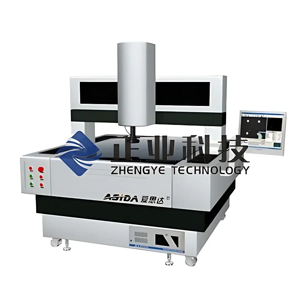
ASIDA Series 2D Vision Coordinate Measuring Machine (CMM) – ASIDA6050A / ASIDA7060A / ASIDA8070A
| Brand | ASIDA |
|---|---|
| Origin | Guangdong, China |
| Model | ASIDA6050A, ASIDA7060A, ASIDA8070A |
| Measurement Range (X×Y×Z) | 600×500×200 mm |
| Optical Magnification | 0.75×–5× Objective + Digital Zoom → Total Magnification: 30×–230× |
| Encoders Resolution | ≤0.001 mm |
| X/Y Linear Accuracy | (3 + L/200) µm (L in mm) |
| Repeatability | ≤±0.003 mm |
| Worktable Size | 650×550 mm / 750×650 mm / 850×750 mm |
| Max Load Capacity | 30 kg |
| Working Distance | 82 mm |
| Software | AISDA MEASURE VMA 3.00.01 (Trilingual: Simplified Chinese, Traditional Chinese, English) |
| Output Formats | DXF, Excel (.xlsx), Word (.docx) |
| OS Compatibility | Windows XP Pro, Windows 7 |
| Minimum PC Requirements | Dual-Core CPU, ≥2 GB RAM, ≥320 GB HDD |
| Power Supply | 220 V AC, 50 Hz |
| Environmental Conditions | Temp. 20 ±2 °C, Humidity 45–75 % RH, Vibration <0.002 g (<15 Hz) |
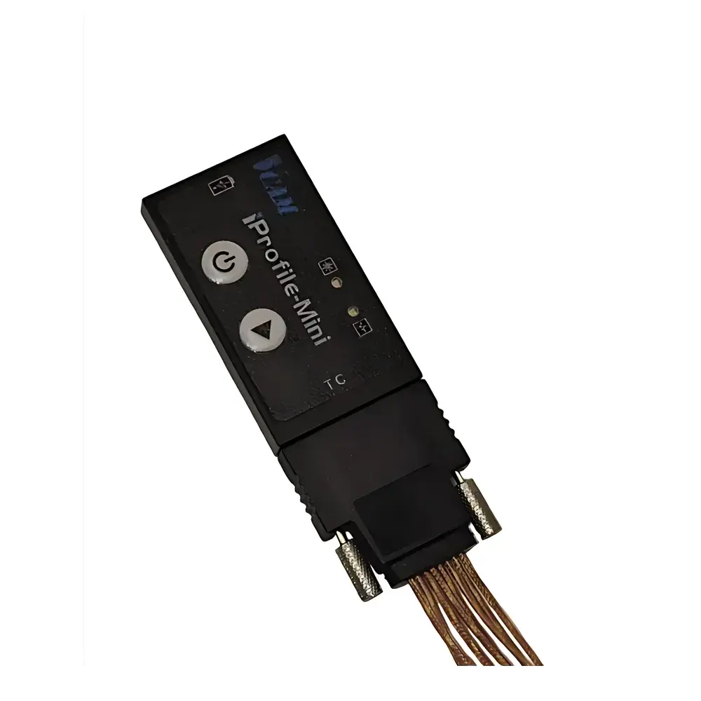
| Optional Accessories | NAVITAR Metrology Lens (USA), RENISHAW TP20 Trigger Probe (UK), KEYENCE LJ-V Series Laser Displacement Sensor (Japan) |
Overview
The ASIDA Series 2D Vision Coordinate Measuring Machine (CMM) is a high-stability, opto-mechanical metrology platform engineered for non-contact, high-resolution dimensional inspection of planar and near-planar components. Operating on the principle of digital image-based coordinate metrology, it captures magnified optical images via a telecentric lens system and high-sensitivity monochrome CMOS sensor, then locates geometric features—points, lines, circles, arcs, rectangles, and contours—through sub-pixel edge detection algorithms. The system determines Cartesian coordinates (X, Y) with traceable uncertainty governed by ISO 10360-2 and ISO 15530-3 standards. While inherently two-dimensional, the platform supports optional tactile probing (e.g., RENISHAW TP20) or laser displacement sensors (e.g., KEYENCE LJ-V) to extend measurement capability into the Z-axis, enabling height mapping, step-height analysis, and basic 3D profile reconstruction. Its granite base and column structure—combined with air-bearing guidance and frictionless drive mechanisms—minimize thermal drift and mechanical hysteresis, ensuring long-term repeatability essential for QC labs operating under GLP or ISO/IEC 17025 accreditation frameworks.
Key Features
- Natural granite base and upright column—providing exceptional rigidity, thermal stability, and resistance to creep deformation over extended operational cycles
- Air-bearing X/Y motion system with precision granite ways—eliminating mechanical wear and maintaining micron-level positional fidelity across full travel range
- Fully friction-driven stage with zero-backlash transmission—ensuring smooth, silent, and repeatable positioning without gear-induced error
- Adjustable cold LED ring illumination—offering uniform, flicker-free, low-heat lighting optimized for edge contrast enhancement and minimizing thermal expansion artifacts
- High-fidelity optical path featuring a 0.75×–5× zoom objective and proprietary telecentric design—delivering consistent magnification, minimal distortion, and high MTF across the entire field of view
- Japanese Panasonic servo motor control with closed-loop feedback—enabling programmable motion profiles, auto-focus synchronization, and coordinated illumination sequencing
- Integrated high-resolution linear encoders (≤0.001 mm resolution)—mounted directly on each axis for real-time position verification independent of drive mechanism
Sample Compatibility & Compliance
The ASIDA 2D CMM accommodates flat, sheet-like, or low-relief parts up to 30 kg and within defined travel envelopes (600×500 mm to 800×600 mm). Typical applications include PCBs, stamped metal parts, injection-molded plastic housings, gaskets, thin-film substrates, and machined flanges. All models comply with electromagnetic compatibility (EMC) requirements per EN 61326-1 and safety standards per EN 61010-1. The measurement uncertainty model adheres to ISO 15530-3 (calibration using calibrated workpieces) and supports traceable calibration via certified gauge blocks and step gauges. When configured with FDA-compliant software modules and audit trail logging, the system meets documentation requirements for regulated environments—including 21 CFR Part 11 compliance when deployed with appropriate IT governance controls (user authentication, electronic signatures, immutable log retention).
Software & Data Management
AISDA MEASURE VMA 3.00.01 is a modular, trilingual metrology software suite supporting both manual and automated measurement routines. It includes geometric tolerance evaluation (GD&T per ASME Y14.5 and ISO 1101), batch reporting, statistical process control (SPC) charting, and customizable report templates. Raw coordinate data and image snapshots are stored in native project files (.vma), while export functions support industry-standard formats: DXF (for CAD comparison), Excel (.xlsx) for SPC integration, and Word (.docx) for audit-ready documentation. The software implements role-based access control, operation logging with timestamped user ID, and configurable data retention policies—facilitating internal quality audits and external assessments under ISO 9001 or IATF 16949. No cloud connectivity is embedded; all data remains on-premise unless explicitly interfaced via secure LAN protocols.
Applications
- Dimensional verification of printed circuit board (PCB) pad locations, solder mask openings, and fiducial alignment marks
- Geometric inspection of automotive stampings—hole positions, slot widths, edge straightness, and angular relationships
- Profile analysis of medical device components such as catheter hubs, syringe barrels, and surgical blade carriers
- Flatness and parallelism assessment of optical mounting plates and semiconductor wafer carriers
- First-article inspection (FAI) reporting in aerospace subcontracting per AS9102 requirements
- Tooling validation for die-cast and injection mold cavities prior to production ramp-up
FAQ
Is this instrument capable of true 3D measurement?
It is fundamentally a 2D vision system. Z-axis measurement requires optional hardware—such as a calibrated tactile probe or laser displacement sensor—and corresponding software licensing.
What calibration standards are recommended for routine verification?
Certified ceramic step gauges (e.g., ±0.5 µm accuracy), NIST-traceable gauge blocks, and calibrated grid plates (e.g., SPI 100 mm × 100 mm) are standard for daily performance checks.
Can the software generate GD&T reports compliant with ASME Y14.5–2018?
Yes—VMA 3.00.01 includes dedicated GD&T modules for position, concentricity, symmetry, profile of a surface, and flatness, with deviation visualization and pass/fail flagging.
Does the system support automated measurement sequences for high-volume inspection?
Yes—programmable measurement routines (PMRs) can be created, saved, and executed with part-to-part registration via pattern matching or fiducial alignment.
What environmental conditions must be maintained for optimal accuracy?
Stable temperature (20 ±2 °C), humidity (45–75 % RH), and vibration isolation (<0.002 g below 15 Hz) are mandatory per ISO 230-2; deviations require revalidation of measurement uncertainty budgets.