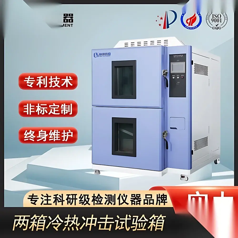
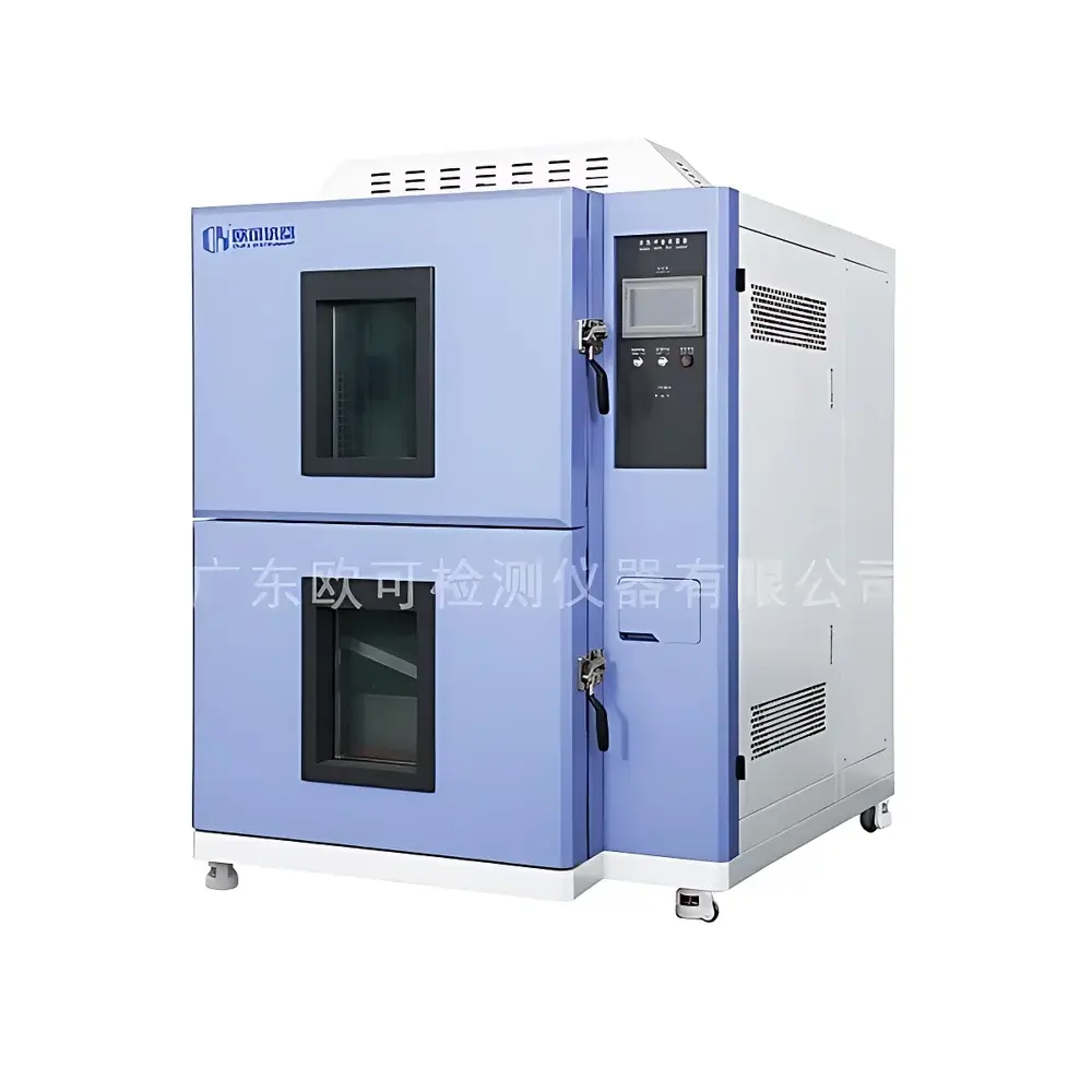
Two-Bay Thermal Shock Test Chamber
| Brand | Other Brands |
|---|---|
| Origin | Imported |
| Manufacturer Type | Authorized Distributor |
| Price | USD 11,200 (FOB) |
Overview
The Two-Bay Thermal Shock Test Chamber is an engineered environmental stress screening (ESS) system designed to evaluate the reliability and structural integrity of electronic components, aerospace assemblies, automotive modules, and advanced packaging materials under rapid, extreme temperature transitions. It operates on the dual-chamber (hot/cold) principle—separating high-temperature and low-temperature zones with a mechanical transfer mechanism—to achieve thermal shock profiles compliant with MIL-STD-810H Method 503.5, IEC 60068-2-14, and JESD22-A104D. Unlike single-chamber ramp-based systems, this configuration eliminates thermal inertia limitations, enabling true step-change transitions (e.g., −65 °C ↔ +150 °C) in ≤15 seconds (transfer time), with dwell stability maintained within ±0.5 °C per zone. The chamber’s core thermodynamic architecture employs the reversed Carnot cycle for both hot and cold circuits, ensuring thermodynamic efficiency, reproducible thermal gradients, and minimal compressor cycling fatigue over extended test durations.
Key Features
- Independent dual-zone design: Separate hot chamber (up to +150 °C) and cold chamber (down to −70 °C), each with dedicated refrigeration, heating, and air circulation subsystems.
- Refrigeration system: Equipped with hermetically sealed French Tecumseh or semi-hermetic German Bitzer compressors; configured in either single-stage air-cooled or cascade air-cooled refrigeration circuits for deep sub-zero capability.
- Air management: Multi-blade centrifugal circulation fans deliver uniform airflow across test volume; adjustable multi-axis air guide vanes ensure spatial temperature uniformity ≤±1.0 °C (at steady state, per IEC 60068-3-5).
- Heating & humidity control: Nickel-chromium alloy finned-tube heaters provide precise thermal response; external stainless-steel surface evaporation humidifier enables controlled RH generation (10–95% RH); condenser coil dew-point dehumidification ensures stable dry-out cycles.
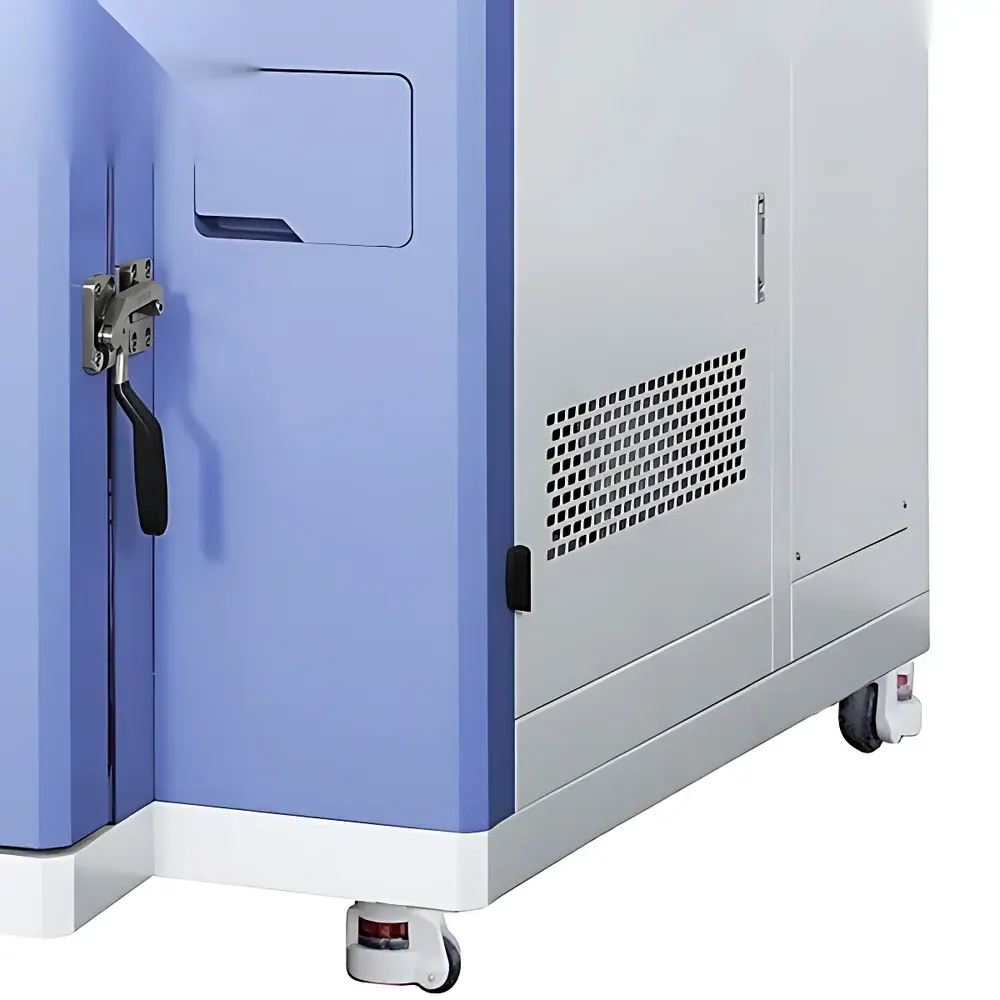
- Water conservation: Concealed reservoir with auto-recirculating pump supplies humidifier; residual condensate recovery minimizes consumable water usage by >40% versus conventional designs.
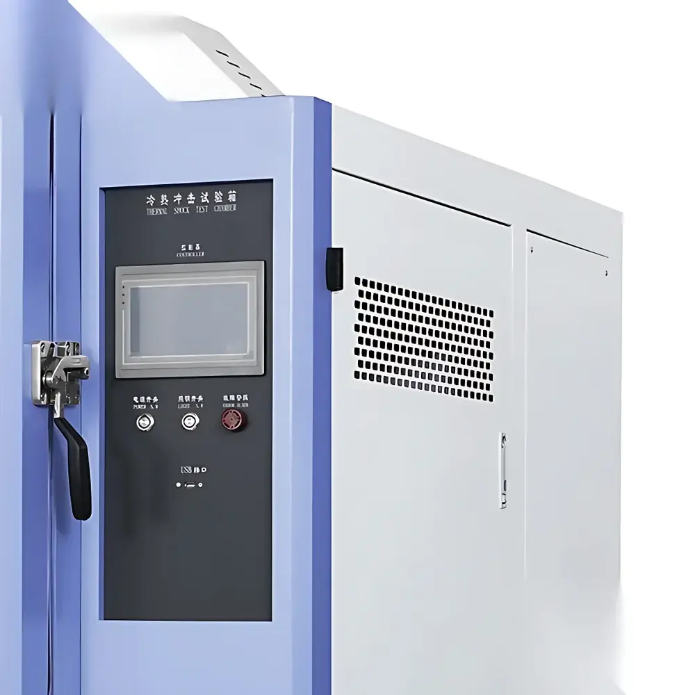
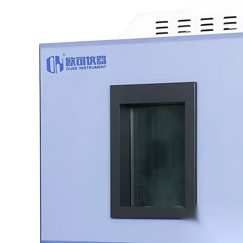
- Structural integrity: Double-wall insulated chamber body with vacuum-sealed polyurethane foam (≥120 mm thickness); electrostatically coated steel exterior; reinforced observation window with anti-fogging dual-pane glass.
Sample Compatibility & Compliance
The chamber accommodates standard test specimens up to 500 mm × 500 mm × 500 mm (W×D×H) with maximum payload ≤30 kg. Internal fixtures support DIN 40041-compliant mounting rails and ISO/IEC 17025 traceable sensor placement. All operational parameters—including transition rate, dwell duration, cycle count, and alarm thresholds—are programmable via embedded controller with audit trail logging. System validation documentation supports IQ/OQ protocols aligned with ISO/IEC 17025 and FDA 21 CFR Part 11 requirements for electronic records and signatures. Calibration certificates are issued per ISO/IEC 17025-accredited laboratories, referencing NIST-traceable reference standards.
Software & Data Management
The integrated controller features a 10.1″ capacitive touchscreen HMI with real-time graphical display of chamber status, setpoint tracking, and alarm history. Test profiles are created using intuitive drag-and-drop logic, supporting up to 999 segments with conditional branching (e.g., “if T-cold < −60 °C, hold 10 min; else trigger fault”). Data export options include CSV, PDF, and XML formats compatible with LIMS integration. Optional Ethernet/IP and Modbus TCP interfaces enable remote monitoring and centralized fleet management. All data logs—including timestamped temperature/humidity values, compressor run hours, and door-open events—are stored with SHA-256 hash integrity verification and user-access-level permissions (admin/operator/viewer).
Applications
This thermal shock chamber is routinely deployed in qualification testing of printed circuit board assemblies (PCBAs), solder joint reliability assessment per IPC-9701, wafer-level packaging validation, battery cell thermal runaway propagation studies, and polymer sealant adhesion endurance evaluation. It serves as a critical tool in accelerated life testing (ALT) programs for automotive ECUs (AEC-Q200), avionics LRUs (RTCA DO-160 Section 4), and medical device sterilization packaging (ISO 11607). Its repeatable thermal transients facilitate failure mode identification—including intermetallic growth, die attach delamination, and CTE-induced microcracking—prior to field deployment.
FAQ
What is the typical transfer time between hot and cold chambers?
Standard transfer time is ≤15 seconds for a 5 kg aluminum mass; actual performance depends on specimen thermal mass and geometry.
Does the system support automated calibration verification?
Yes—the controller includes built-in self-diagnostic routines for sensor drift detection and supports periodic verification using external reference probes per ISO/IEC 17025 procedures.
Can the chamber operate continuously for extended qualification tests?
Designed for 7×24 operation with redundant safety interlocks, thermal cutouts, and predictive maintenance alerts based on compressor duty cycle analytics.
Is compliance documentation provided for regulatory submissions?
Full validation package—including FAT/SAT reports, uncertainty budgets, and traceable calibration certificates—is available upon request for FDA, EMA, or notified body review.
What maintenance intervals are recommended?
Compressor oil analysis every 2,000 operating hours; evaporator coil cleaning quarterly; full system performance verification annually per manufacturer’s maintenance schedule.


