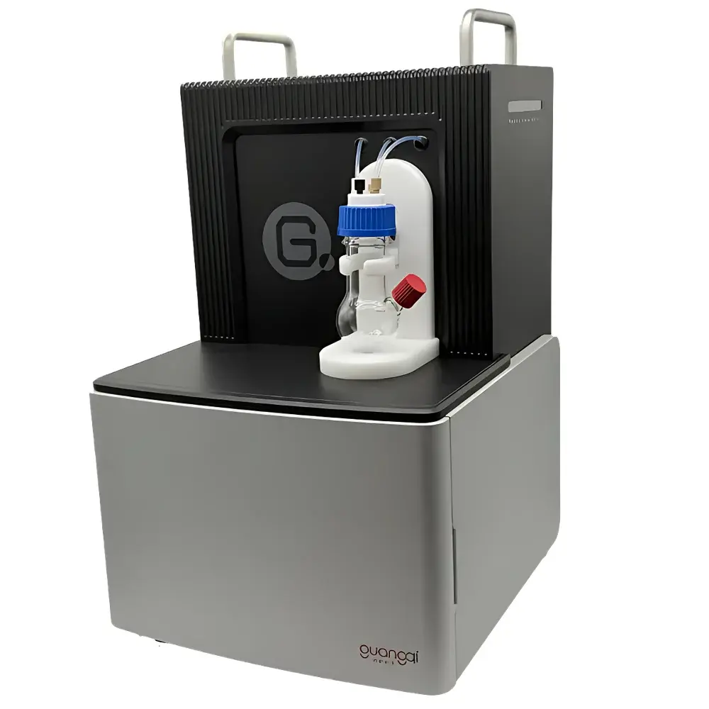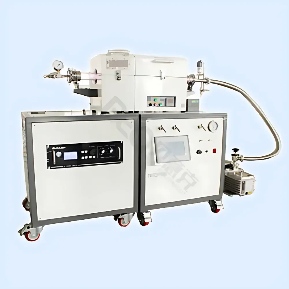
BEQ Micro PECVD System
| Brand | BEQ |
|---|---|
| Origin | Anhui, China |
| Manufacturer Type | Authorized Distributor |
| Product Origin | Domestic (China) |
| Model | Micro PECVD |
| Heating Method | Hot-Wall |
| Base Vacuum | 5 × 10⁻¹ Pa |
| Operating Pressure Range | 1.01325 × 10⁵ Pa to 1.33 × 10⁻² Pa |
| RF Power Output | 0–150 W |
| RF Interface | 50 Ω, N-type female |
| Power Stability | ≤5 W |
| Harmonic Content | ≤−50 dBc |
| Max. Heating Temperature | 1200 °C (Continuous Use ≤1100 °C) |
| Effective Chamber Dimensions | Φ25 mm / Φ50 mm (Customizable Tube Diameter) |
| Chamber Material | Alumina + High-Temperature Ceramic Fiber |
| Thermocouple Type | K-type |
| Temperature Control Accuracy | ±1 °C |
| Control Mode | 30-Stage Programmable PID with Auto-Tuning |
| Heating Zone Length | 230 mm |
| Heating Element | Resistance Wire |
| Power Supply | Single-phase, 220 V, 50/60 Hz |
| Total System Power | 1 kW |
| Pumping Speed | 10 m³/h |
| Ultimate Vacuum (with Pump) | 5 × 10⁻¹ Pa |
| Vacuum Gauge Range | −0.1 to 0.15 MPa (0.01 MPa/div) |
| Mass Flow Controllers | Triple-channel, Stainless Steel Dual-Ferrule Fittings |
| Standard N₂ Flow Ranges | 200 / 500 / 1000 sccm (Customizable) |
| MFC Accuracy | ±1.5% FS |
| Linearity | ±1% FS |
| Repeatability | ±0.2% FS |
| Response Time (Gas) | 1–4 s |
| (Electrical) | 10 s |
| Working Pressure Drop | 0.1–0.5 MPa |
| Max. Inlet Pressure | 3 MPa |
| Cooling | Forced Air |
| Ambient Temp. Range | 5–45 °C |
| Relative Humidity | ≤85% RH |
| Noise Level | ≤50 dB(A) |
| Vacuum Interface | KF25 (Inlet & Exhaust) |
| Vacuum Connection | Bellows + Manual Gate Valve |
Overview
The BEQ Micro PECVD System is a compact, benchtop plasma-enhanced chemical vapor deposition instrument engineered for precise, reproducible thin-film synthesis in semiconductor research and development laboratories. Utilizing very high frequency (VHF, typically 60 MHz) plasma excitation, the system enables efficient dissociation of precursor gases at reduced substrate temperatures—critical for temperature-sensitive substrates such as flexible polymers, pre-patterned wafers, or devices with low thermal budget constraints. Unlike conventional RF (13.56 MHz) PECVD systems, the VHF configuration yields higher electron density and lower ion energy, promoting high deposition rates (up to 10 Å/s) while minimizing plasma-induced damage. The hot-wall heating architecture ensures uniform radial and axial thermal profiles across the reaction zone, supporting consistent film stoichiometry and stress control. Designed for integration into cleanroom-compatible workflows, the system operates within a controlled pressure range spanning from atmospheric (1.01325 × 10⁵ Pa) down to 1.33 × 10⁻² Pa—enabling both low-pressure plasma processing and near-atmospheric deposition modes.
Key Features
- VHF plasma source (60 MHz) with 0–150 W adjustable output, N-type female 50 Ω interface, and harmonic suppression (<−50 dBc) for stable, low-noise plasma generation
- Hot-wall furnace with dual-zone thermal design: alumina-lined chamber and high-purity ceramic fiber insulation; maximum operating temperature 1100 °C (rated to 1200 °C)
- Precision temperature control via 30-segment programmable PID with auto-tuning and ±1 °C stability over extended runs
- Triple-channel mass flow controller (MFC) system with stainless steel dual-ferrule fittings, calibrated for N₂ (200/500/1000 sccm options), ±1.5% full-scale accuracy, and <2% total process gas error
- Integrated low-vacuum pumping station (10 m³/h rotary vane pump) achieving base pressure ≤5 × 10⁻¹ Pa; KF25 vacuum flanges with bellows and manual gate valve for leak-tight operation
- Modular gas delivery architecture supporting optional precursor injection modules—including direct spray nozzles for localized reactant delivery into the plasma zone
- Comprehensive safety interlocks: overtemperature cutoff, RF arc detection, vacuum loss shutdown, and real-time power monitoring
Sample Compatibility & Compliance
The Micro PECVD accommodates substrates up to Φ50 mm (customizable tube diameters available), including silicon wafers, glass slides, quartz, metal foils, and polymer films. Its compact chamber geometry and uniform plasma distribution—enabled by multi-point RF feedthrough and optimized gas inlet manifolds—deliver film thickness uniformity ≤±8% across full wafers and inter-substrate variation <±2% under identical process conditions. The system complies with IEC 61000-6-3 (EMC emission limits) and IEC 61000-6-2 (immunity standards). All electrical components meet CE marking requirements. While not certified for GMP production environments, its hardware architecture and repeatable process execution support GLP-aligned R&D documentation, and its programmable recipe storage facilitates audit-ready traceability when integrated with external LIMS or ELN platforms.
Software & Data Management
The system operates via a dedicated industrial HMI panel featuring 4-digit LED displays for real-time readout of pressure, temperature, RF power, and MFC flow rates. All process parameters—including ramp rates, dwell times, gas sequences, and plasma ignition thresholds—are stored as editable recipes with timestamped execution logs. While the base configuration does not include PC-based software, RS485 and analog 0–10 V I/O ports enable integration with third-party SCADA systems or custom LabVIEW/Python automation frameworks. For regulated environments, users may implement 21 CFR Part 11-compliant electronic signatures and audit trails using validated external data acquisition software—provided system-level access controls and data integrity safeguards are externally enforced.
Applications
- Growth of silicon nitride (SiNx), silicon dioxide (SiO2), and amorphous silicon (a-Si:H) passivation layers for photovoltaic cells and MEMS devices
- Deposition of hydrogenated carbon films (e.g., a-C:H) for tribological coatings and biocompatible surfaces
- Low-temperature synthesis of transparent conductive oxides (TCOs) on plastic substrates for flexible electronics
- Plasma surface functionalization of polymers prior to metallization or bonding
- Rapid prototyping of dielectric stacks in academic and industrial semiconductor process development labs
FAQ
What is the typical deposition rate for SiNx under standard VHF-PECVD conditions?
Typical deposition rates range from 5–10 Å/s depending on RF power (80–150 W), pressure (0.1–10 Pa), and precursor gas ratio (e.g., NH3/SiH4). Rate linearity vs. power is confirmed across multiple lots.
Can the system be upgraded to support remote monitoring or Ethernet connectivity?
Yes—RS485 Modbus RTU is standard; optional Ethernet-to-serial gateways and OEM API SDKs are available upon request for integration with factory MES or lab automation networks.
Is the chamber compatible with corrosive precursors such as BCl3 or WF6?
Standard configuration uses stainless steel and alumina wetted parts; for aggressive chemistries, optional quartz-lined chambers and corrosion-resistant MFCs (e.g., Hastelloy valves) can be specified during order placement.
Does the system include vacuum leak-check capability?
No built-in helium leak detector is included, but the KF25 ports and metal-sealed flanges support external connection to standard检漏 instruments; base pressure recovery time (<30 min from atmosphere to 5×10⁻¹ Pa) serves as an operational leak indicator.
What maintenance intervals are recommended for the RF generator and vacuum pump?
RF amplifier requires annual calibration verification; vacuum pump oil should be changed every 500 operating hours or per manufacturer’s specification (1.1 L capacity). Full preventive maintenance checklist is provided in the technical manual.