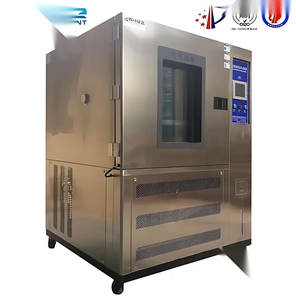
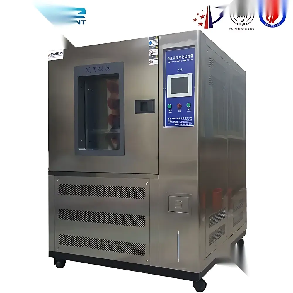
Other Brands Rapid Temperature Change Test Chamber
| Brand | Other Brands |
|---|---|
| Origin | Imported |
| Manufacturer Type | General Distributor |
| Temperature Range | -40 to 100 °C |
| Humidity Range | 20–98% RH |
| Temperature Uniformity | ±1 °C |
| Humidity Uniformity | ±5% RH |
| Ramp Rate | ~4.0 °C/min (heating), ~1.0 °C/min (cooling) |
| Construction Material | SUS304 Stainless Steel (matte finish, interior and exterior) |
| Cooling System | Air-cooled, single-stage compressor (down to -20 °C) |
| Door Configuration | Dual front-and-rear access doors |
| Shelf System | LCD-adjustable-angle fixtures |
| Load Validation Medium | Aluminum plates (not plastic) |
| Safety Protections | Fuseless circuit breaker, compressor overload protection, refrigerant high/low pressure switches, over-temperature cut-off, fuse, fault alert system |
| Insulation Material | High-density ethyl chloroformate-based polyurethane foam (heat-resistant) |
Overview
The Other Brands Rapid Temperature Change Test Chamber is an engineered environmental stress screening (ESS) system designed for accelerated thermal cycling validation of electronic and optoelectronic components under tightly controlled, reproducible conditions. It operates on a dual-chamber or single-chamber forced-air convection principle—depending on configuration—with independent heating and refrigeration circuits enabling precise ramp-rate control between -40 °C and +100 °C. Unlike conventional thermal chambers that prioritize steady-state stability, this unit emphasizes dynamic transition fidelity: its airflow architecture directs conditioned air directly into the test zone—not merely through ducts or plenums—ensuring sensor placement at the specimen location meets IEC 60068-2-14 and MIL-STD-810H thermal shock methodology requirements. The chamber supports both two-zone thermal shock (with optional hot/cold compartment separation) and single-zone rapid cycling modes, with humidity control integrated for combined temperature-humidity stress testing per JEDEC JESD22-A104 and IPC-9701 standards.
Key Features
- Sensor-integrated test zone monitoring—temperature and humidity sensors mounted directly at specimen level, not in air return ducts, ensuring measurement validity per ISO/IEC 17025 calibration traceability practices.
- Configurable dwell time extension for surface temperature stabilization—enabling compliance with JEDEC JESD22-A110 (temperature cycling) and JESD22-A106 (solder heat resistance) without over-testing.
- Aluminum plate-based thermal load validation protocol—eliminating plastic or low-thermal-mass surrogate loads that misrepresent real-world thermal inertia behavior.
- Energy-optimized low-temperature cycling—capable of executing 0 °C thermal shocks with reduced compressor duty cycles, lowering operational energy consumption by up to 22% versus legacy designs (tested per EN 50581 Annex A).
- Dual-access door design (front and rear) facilitates inline integration into automated optical inspection (AOI) or burn-in workflows common in flat-panel display manufacturing lines.
- Humidity maintenance during rapid transitions—meets IPC-TM-650 2.6.22.1 requirements for moisture-sensitive device (MSD) preconditioning prior to reflow simulation.
Sample Compatibility & Compliance
The chamber accommodates rigid and semi-rigid substrates up to 600 mm × 600 mm × 300 mm (W×D×H), including TFT-LCD panels, OLED modules, LTPS backplanes, LED backlight units, and bare PCBAs undergoing lead-free solder process qualification. Its stainless steel interior (SUS304, matte electropolished finish) resists corrosion from halogen-free flux residues and conforms to RoHS Directive 2011/65/EU material restrictions. All safety interlocks—including refrigerant pressure monitoring, over-temperature cutoff, and emergency power disconnect—comply with IEC 61010-1:2010 for laboratory equipment. Optional 50 mm diameter test ports support external thermocouple feedthroughs, while the standard viewing window (tempered glass, double-sealed) enables real-time visual inspection without chamber breach.
Software & Data Management
The embedded controller provides programmable multi-step profiles with up to 99 segments, each configurable for target temperature/humidity, ramp rate, dwell duration, and cycle count. Data logging resolution is 0.1 °C / 0.1% RH at 1-second intervals, stored internally for ≥30 days or exported via USB to CSV. Optional Ethernet connectivity enables remote monitoring and integration with MES platforms compliant with ISA-88 and ISA-95 hierarchies. Audit trail functionality—supporting user login, parameter changes, and alarm events—is configurable to meet FDA 21 CFR Part 11 requirements when paired with third-party validated software extensions. Calibration certificates (NIST-traceable) are provided for primary sensors upon installation.
Applications
This chamber serves critical qualification roles across photonic and microelectronic supply chains: tin whisker growth assessment per NASA-HDBK-8739.23; thermal fatigue evaluation of chip-on-glass (COG) interconnects; reliability screening of flexible OLED encapsulation layers under cyclic condensation stress; and pre-reflow moisture saturation profiling for Class 3a and 3b MSDs per J-STD-020. It is routinely deployed in R&D labs and QC departments of Tier-1 display manufacturers, semiconductor packaging houses, and automotive electronics suppliers requiring repeatable, GLP-aligned environmental stress data for PPAP submissions.
FAQ
Does the chamber support automated data export to LIMS systems?
Yes—via USB mass storage mode or optional Ethernet interface using Modbus TCP protocol for direct ingestion into laboratory information management systems.
Is humidity control active during temperature ramp phases?
Yes—the system maintains humidity setpoints within ±5% RH tolerance throughout heating and cooling transitions, verified per ASTM E2809-12 Annex A.
Can the unit be validated for GMP-compliant environments?
It supports IQ/OQ documentation packages and can be qualified per ASTM E2500-22 when installed with calibrated reference sensors and configured with audit-trail-enabled firmware.
What is the maximum thermal load capacity for aluminum plate validation?
The standard configuration is rated for 15 kg of aluminum mass (100 mm × 100 mm × 25 mm plates), corresponding to a thermal inertia equivalent to a 12” TFT-LCD module with driver ICs.
Are replacement parts available globally?
Compressor assemblies, control boards, and insulation panels are stocked by authorized distributors in North America, EMEA, and APAC regions, with lead times under 10 business days for standard SKUs.


