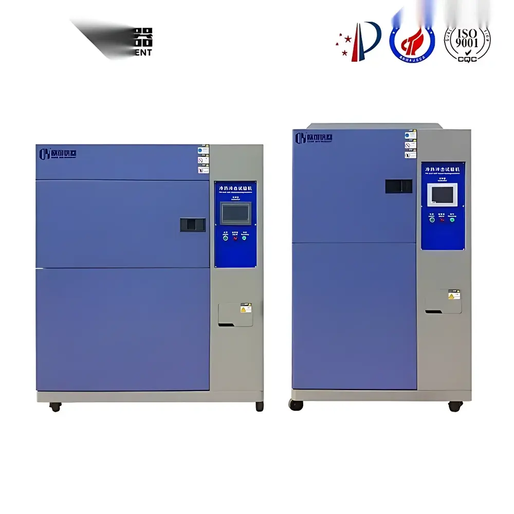
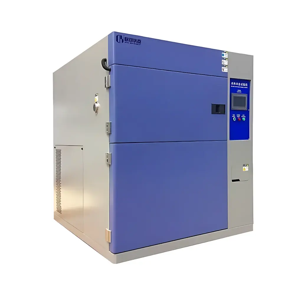
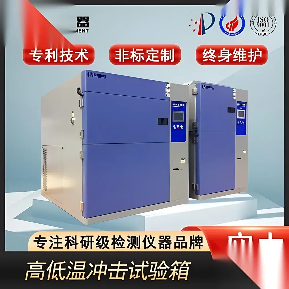
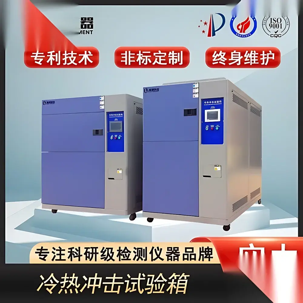
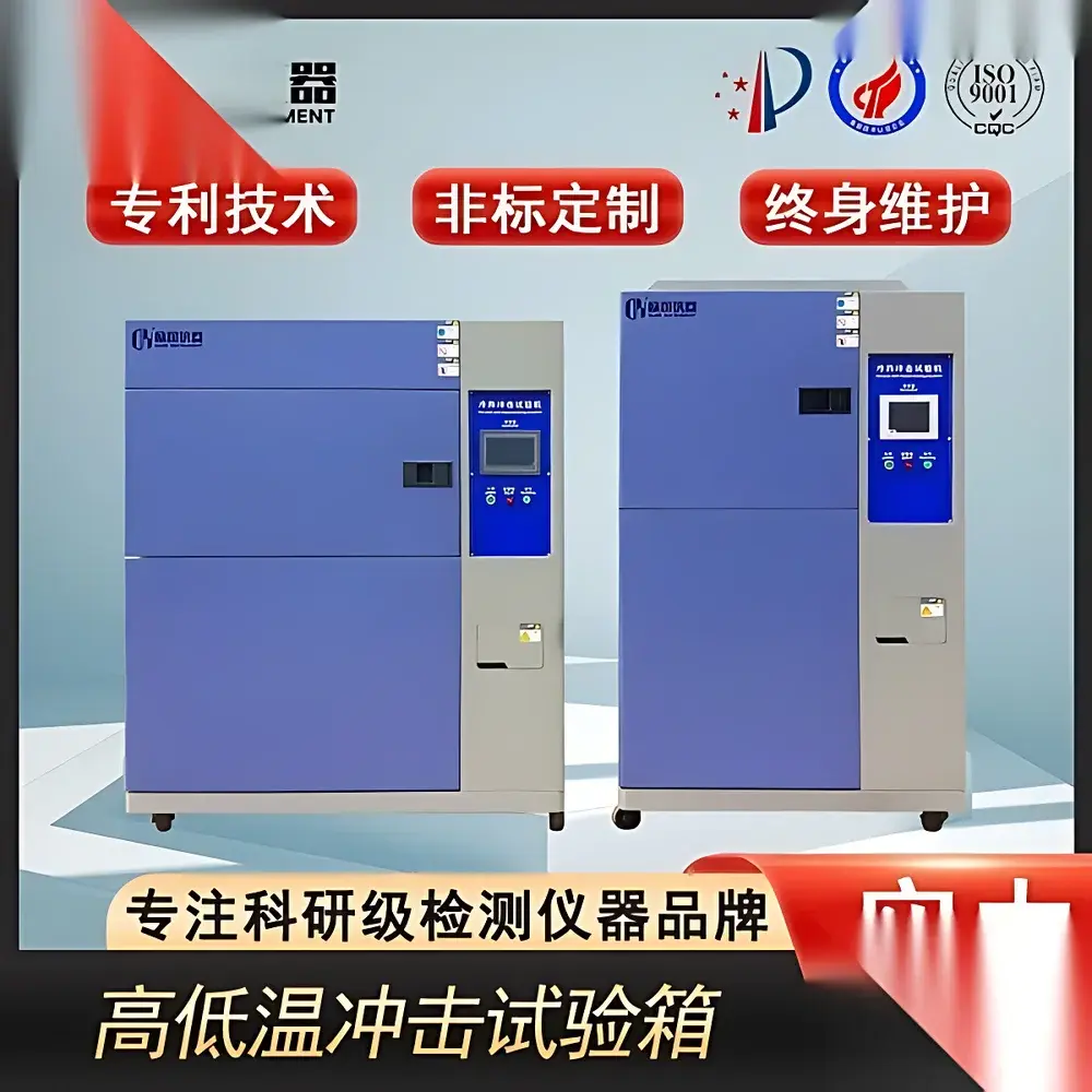
Two-Chamber Thermal Shock Test Chamber
| Brand | Other Brands |
|---|---|
| Origin | Imported |
| Manufacturer Type | General Distributor |
| Price | USD 11,200 (FOB) |
| Cooling System | Dual-Stage Cascade Refrigeration with Imported German Semi-Hermetic Compressors |
| Cooling Water Requirement | External 10 m³/h Cooling Tower (User-Supplied) |
| Compliance | GB/T 2423.1–2008, GB/T 2423.2–2008, GB/T 2423.22–2002, GJB 150.5–2009, IEC 60068-2-14, MIL-STD-810G Method 503.5, QC/T 17–1992, EIA-364-32 |
Overview
The Two-Chamber Thermal Shock Test Chamber is an engineered environmental simulation system designed to evaluate material and component reliability under rapid, extreme temperature transitions. It operates on the principle of physical thermal shock—inducing abrupt dimensional stress via controlled, high-rate temperature excursions between two isolated chambers: one maintained at high temperature (typically +150 °C) and the other at low temperature (down to –70 °C). Unlike single-chamber or three-chamber configurations, the two-chamber design employs a horizontal transfer mechanism that physically moves test specimens between thermally stabilized zones, achieving transition times as short as 5–10 seconds (measured per IEC 60068-2-14, Method N). This architecture eliminates thermal inertia limitations inherent in air-mixing systems and ensures precise, repeatable exposure profiles essential for qualification testing in aerospace, automotive electronics, semiconductor packaging, and defense applications.
Key Features
- Dual independent chamber architecture with separate heating and refrigeration circuits—enabling simultaneous high- and low-temperature stabilization
- Cascade refrigeration system utilizing imported German semi-hermetic compressors and environmentally compliant R404A/R23 refrigerant pairs for stable operation down to –70 °C
- Water-cooled condensing unit requiring external 10 m³/h cooling tower capacity (user-supplied); optimized for continuous-duty thermal cycling
- Energy modulation control logic regulating refrigerant flow and compressor load—reducing power consumption by up to 25% during partial-load operation without compromising ramp rate fidelity
- Stainless-steel transfer carriage with pneumatic actuation and position feedback sensors—ensuring repeatable specimen positioning and minimizing dwell time uncertainty
- Integrated over-temperature, over-pressure, and refrigerant leak detection with hardware interlocks compliant with IEC 61000-6-2 EMC and UL 61010-1 safety standards
Sample Compatibility & Compliance
The chamber accommodates standard test specimens up to 500 mm × 500 mm × 500 mm (W×D×H), with optional custom payload fixtures available for PCB assemblies, molded connectors, battery modules, and hermetically sealed optoelectronic housings. All operational protocols adhere strictly to internationally recognized qualification standards—including MIL-STD-810G Method 503.5 (Temperature Shock), IEC 60068-2-14 (Test Nb: Change of Temperature), GJB 150.5–2009 (Military Equipment Environmental Testing), and QC/T 17–1992 (Automotive Component Environmental Durability). Calibration traceability follows ISO/IEC 17025 requirements, with documented uncertainty budgets for temperature uniformity (±1.5 °C) and transition time (±0.5 s) across the working volume.
Software & Data Management
Control and data acquisition are managed via a real-time embedded controller running proprietary firmware compliant with FDA 21 CFR Part 11 Annex 11 principles. The system supports audit-trail-enabled user authentication, electronic signatures, and immutable event logging—including chamber status, setpoint deviations, transfer timing, and alarm history. Export formats include CSV and XML for integration into LIMS platforms or statistical process control (SPC) environments. Optional Ethernet/IP or Modbus TCP interfaces enable remote monitoring and synchronization with enterprise MES systems. All test profiles—including dwell times, ramp rates, cycle counts, and pass/fail thresholds—are programmable and stored with version-controlled revision history.
Applications
This test chamber is routinely deployed in failure analysis laboratories and product validation centers for assessing thermal fatigue resistance in solder joints (IPC-J-STD-020), delamination susceptibility in multilayer ceramic capacitors (MLCCs), glass-to-metal seal integrity in vacuum feedthroughs, and coefficient-of-thermal-expansion (CTE) mismatch effects in heterogeneous packaging structures. It serves as a primary qualification tool for suppliers to Tier-1 automotive OEMs (per ISO/TS 16949), avionics integrators (per DO-160 Section 4), and medical device manufacturers subject to ISO 13485 and IEC 60601-1 clause 11.12 (Environmental Stress Screening).
FAQ
What is the typical temperature transition time between chambers?
Transition time from +150 °C to –70 °C (or vice versa) is ≤10 seconds for a standard 1 kg aluminum mass, measured per IEC 60068-2-14, Clause 6.2. Actual performance depends on specimen thermal mass and geometry.
Is the system compatible with GLP/GMP-compliant validation protocols?
Yes—the controller firmware includes IQ/OQ documentation templates, calibration certificate management, and full electronic audit trail functionality meeting ALCOA+ data integrity criteria.
Does the chamber require dedicated electrical infrastructure?
It operates on three-phase 380 VAC ±10%, 50 Hz power with a minimum circuit rating of 63 A; voltage stability must be maintained within ±2% during compressor startup cycles.
Can test profiles be exported for third-party analysis?
All raw temperature/time data, event logs, and alarm records export in timestamped CSV format with UTC synchronization and configurable sampling intervals (100 ms to 10 s).
What maintenance intervals are recommended for the cascade refrigeration system?
Compressor oil analysis and refrigerant moisture testing every 12 months; evaporative condenser coil cleaning every 6 months; full system leak check and charge verification annually per ASHRAE Guideline 3-2021.


