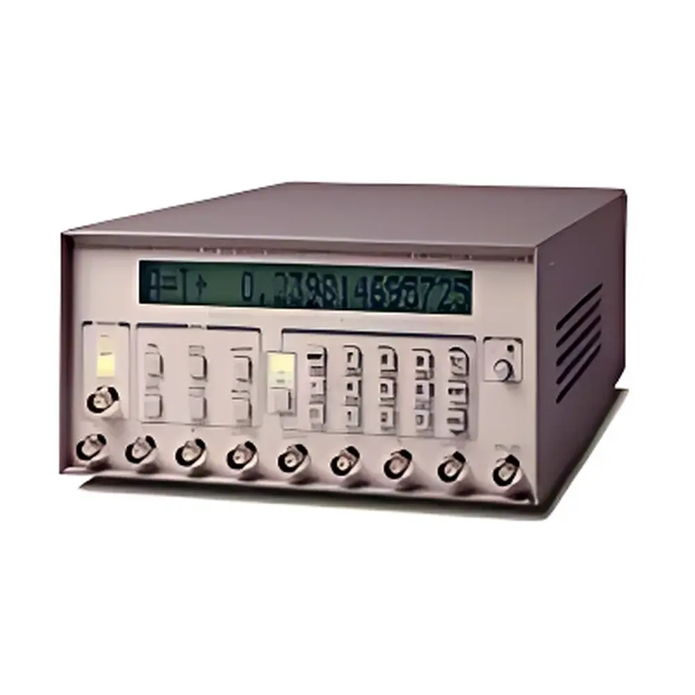
DG535 Four-Channel Digital Delay/Pulse Generator
| Brand | SRS (Stanford Research Systems) |
|---|---|
| Origin | USA |
| Model | DG535 |
| Delay Channels | 4 independent |
| Pulse Outputs | 2 fully programmable |
| Delay Resolution | 5 ps |
| RMS Jitter | 50 ps |
| Max Delay Range | 1000 s |
| Output Voltage Range | Adjustable amplitude and offset, up to ±35 V (with optional high-voltage module) |
| Rise/Fall Time | <100 ps (with optional module) |
| Standard Interface | GPIB (IEEE-488.2), RS-232 available via adapter |
| Compliance | CE, RoHS |
Overview
The DG535 Four-Channel Digital Delay/Pulse Generator is a precision timing instrument engineered for synchronization, triggering, and gating applications in advanced scientific laboratories. Designed and manufactured by Stanford Research Systems (SRS), a U.S.-based leader in test and measurement instrumentation, the DG535 implements digital delay synthesis with direct digital synthesis (DDS)-derived timing control to achieve sub-picosecond resolution and exceptional temporal stability. Its core architecture utilizes high-speed CMOS logic and temperature-compensated crystal oscillators, ensuring low phase noise and minimal thermal drift over extended operation. The device operates as a deterministic timebase controller—capable of generating precisely timed triggers, gates, and pulse trains across four independent delay channels and two fully programmable pulse outputs. It serves as a foundational timing engine in ultrafast spectroscopy (e.g., pump-probe, time-resolved fluorescence), laser system synchronization (Q-switching, cavity dumping), particle accelerator RF timing, quantum optics experiments (single-photon detection gating), and pulsed NMR/ESR setups where nanosecond-to-second scale temporal coordination is critical.
Key Features
- Four independent digital delay channels, each configurable with user-defined delay, width, and polarity
- Two fully programmable pulse output channels supporting arbitrary pulse train generation, burst modes, and external modulation
- 5 ps minimum delay resolution—enabling precise alignment of optical, electronic, or mechanical events at the picosecond level
- 50 ps RMS jitter (typ.) over full temperature range (0–50 °C), verified per IEEE Std 1139 statistical methods
- Delay range spanning 0 to 1000 seconds, supporting both ultrafast (<1 ns) and long-interval (≥1 s) timing protocols
- Output voltage adjustable from −10 V to +10 V standard; optional ±35 V high-voltage module available for driving photomultiplier tube gates or electro-optic modulators
- Sub-100 ps rise/fall times achievable with optional fast-edge output module (requires external 50 Ω termination)
- GPIB (IEEE-488.2) interface standard; RS-232 support via optional adapter for legacy system integration
- Front-panel keypad and LCD display enable standalone operation without host computer dependency
Sample Compatibility & Compliance
The DG535 is designed for integration into diverse experimental configurations including vacuum chambers, cryogenic stages, and electromagnetic-shielded enclosures. Its TTL/CMOS-compatible outputs ensure seamless interfacing with commercial lasers (e.g., Ti:sapphire, diode-pumped solid-state), photodetectors (APDs, PMTs), data acquisition systems (e.g., PCIe digitizers), and motion controllers. All electrical interfaces comply with IEC 61000-4 immunity standards for electrostatic discharge (ESD), radiated RF fields, and fast transient bursts. The unit bears CE marking and conforms to RoHS Directive 2011/65/EU for hazardous substance restrictions. While not certified for medical or industrial safety-critical use, its timing performance meets requirements for GLP-compliant research environments when operated within specified ambient conditions (20–25 °C, <70% RH non-condensing).
Software & Data Management
SRS provides native LabVIEW VIs, MATLAB instrument drivers, and Python (PyVISA) examples for automated control and script-based experiment sequencing. All timing parameters—including delay values, trigger sources, and output logic states—are programmatically readable and writable via GPIB SCPI commands (e.g., DELAY1:TIME? 1.234567890123456E-09). The DG535 supports full audit-trail logging when integrated with compliant data acquisition frameworks; timestamped configuration changes can be exported in CSV or XML format for traceability. Though it does not implement FDA 21 CFR Part 11 electronic signature functionality natively, its deterministic behavior and repeatable command-response latency make it suitable for IQ/OQ validation protocols under ISO/IEC 17025-accredited calibration workflows.
Applications
- Synchronization of ultrafast laser systems with streak cameras or single-shot oscilloscopes
- Time-gated detection in time-resolved Raman, fluorescence lifetime imaging (FLIM), and phosphorescence decay measurements
- Triggering of high-speed camera shutters (e.g., ICCD, sCMOS) in combustion diagnostics or plasma physics
- Phase-locked pulse generation for coherent control experiments in atomic/molecular physics
- Multi-channel stimulus delivery in electrophysiology and neural interface studies
- Calibration reference source for time-of-flight mass spectrometers and particle detectors
FAQ
What is the maximum delay accuracy specification over temperature?
The DG535 maintains ±(5 ps + 0.1 ppm × delay setting) absolute accuracy from 0 to 50 °C, referenced to its internal 10 MHz oven-controlled crystal oscillator (OCXO).
Can multiple DG535 units be synchronized to a common master clock?
Yes—via the rear-panel REF IN/OUT BNC connectors, enabling daisy-chained or star-topology distribution of a 10 MHz reference signal with sub-100 ps skew between units.
Is the DG535 compatible with modern USB-based control environments?
While GPIB remains the primary interface, USB-to-GPIB adapters (e.g., National Instruments GPIB-USB-HS) are fully supported; no native USB interface is built in.
Does the device support external trigger repetition rate modulation?
Yes—the DG535 accepts TTL-level external triggers at rates up to 10 MHz and allows programmable retriggering with variable inter-pulse intervals using its internal sequencer.
How is calibration maintained over time?
SRS recommends annual recalibration against a traceable time standard (e.g., NIST-calibrated time interval analyzer); factory calibration certificates include uncertainty budgets per ISO/IEC 17025 Annex A.


")