Dynamic Photoelasticity Teaching Demonstration System
| Brand | Olympus |
|---|---|
| Origin | Shanghai, China |
| Manufacturer Type | Authorized Distributor |
| Country of Origin | China |
| Model | Custom-Educational Variant |
| Pricing | Available Upon Request |
Overview
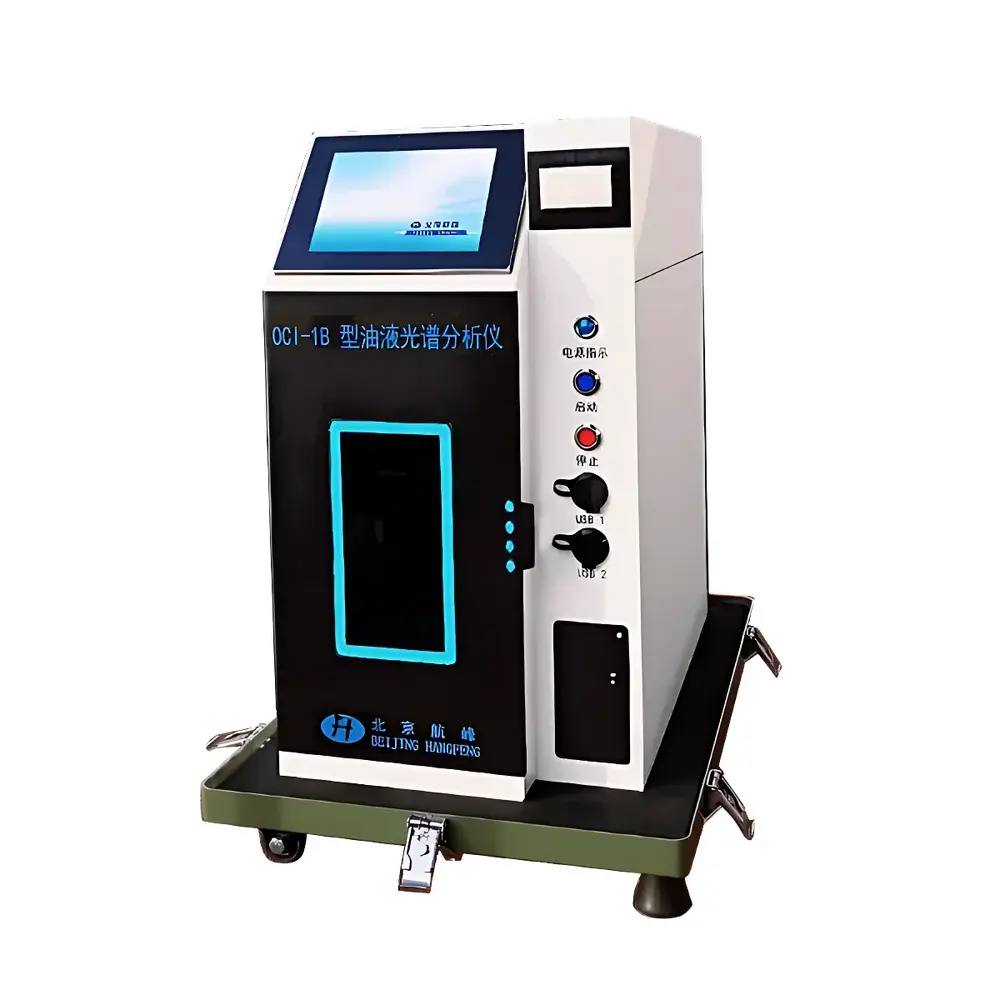
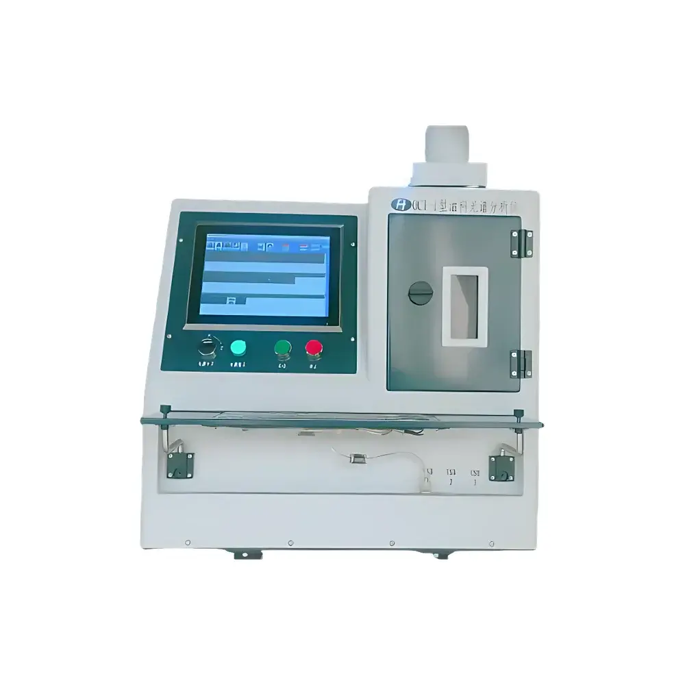
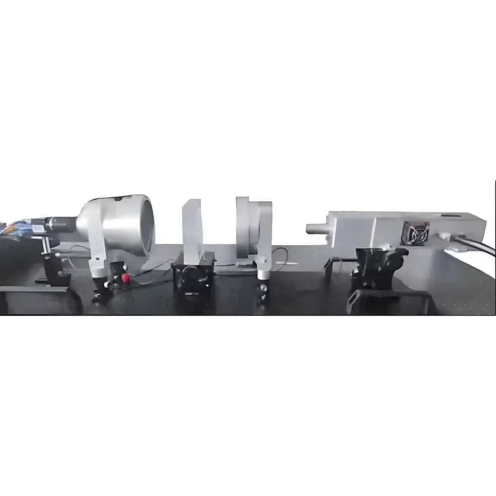
The Dynamic Photoelasticity Teaching Demonstration System is a purpose-built optical-mechanical instrumentation platform engineered for real-time visualization and qualitative analysis of stress wave propagation, diffraction, and scattering phenomena in transparent or semi-transparent elastic solids under dynamic loading. Unlike static photoelastic setups, this system integrates pulsed ultrasonic excitation (typically 0.5–5 MHz) with high-speed polarized light imaging to capture transient stress fields as time-resolved fringe patterns—enabling direct observation of wavefront evolution, mode conversion (e.g., longitudinal-to-shear), boundary reflections, and interference effects. Developed in collaboration with the Institute of Acoustics, Chinese Academy of Sciences, the system adheres to fundamental principles of dynamic photoelasticity based on the stress-optic law (Δn ∝ σ₁ − σ₂), where induced birefringence in photoelastic models correlates linearly with principal stress differences. Its compact benchtop architecture (W × D × H: 420 × 310 × 280 mm), modular optical path, and integrated USB 3.0 camera interface make it suitable for undergraduate mechanics laboratories, graduate-level experimental solid mechanics courses, and applied acoustics training modules.
Key Features
- Real-time dynamic fringe acquisition at up to 10,000 fps (configurable), synchronized with programmable ultrasonic burst excitation (pulse width: 0.1–10 µs, repetition rate: 1–10 kHz)
- Dual-path polariscope configuration with adjustable quarter-wave plates, precision rotatable analyzers, and LED-illuminated collimated white-light source (520–650 nm spectral range)
- Pre-calibrated photoelastic polymer sample kits (e.g., polycarbonate, epoxy resin) with standardized geometries (notched beams, circular holes, cantilever plates) for quantitative stress concentration factor validation
- Integrated hardware trigger interface supporting external function generators, oscilloscopes, or laser Doppler vibrometers for multi-sensor correlation studies
- Robust aluminum-alloy optical breadboard base with kinematic mounts, vibration-damped feet, and ESD-safe enclosure compliant with IEC 61000-4-2
Sample Compatibility & Compliance
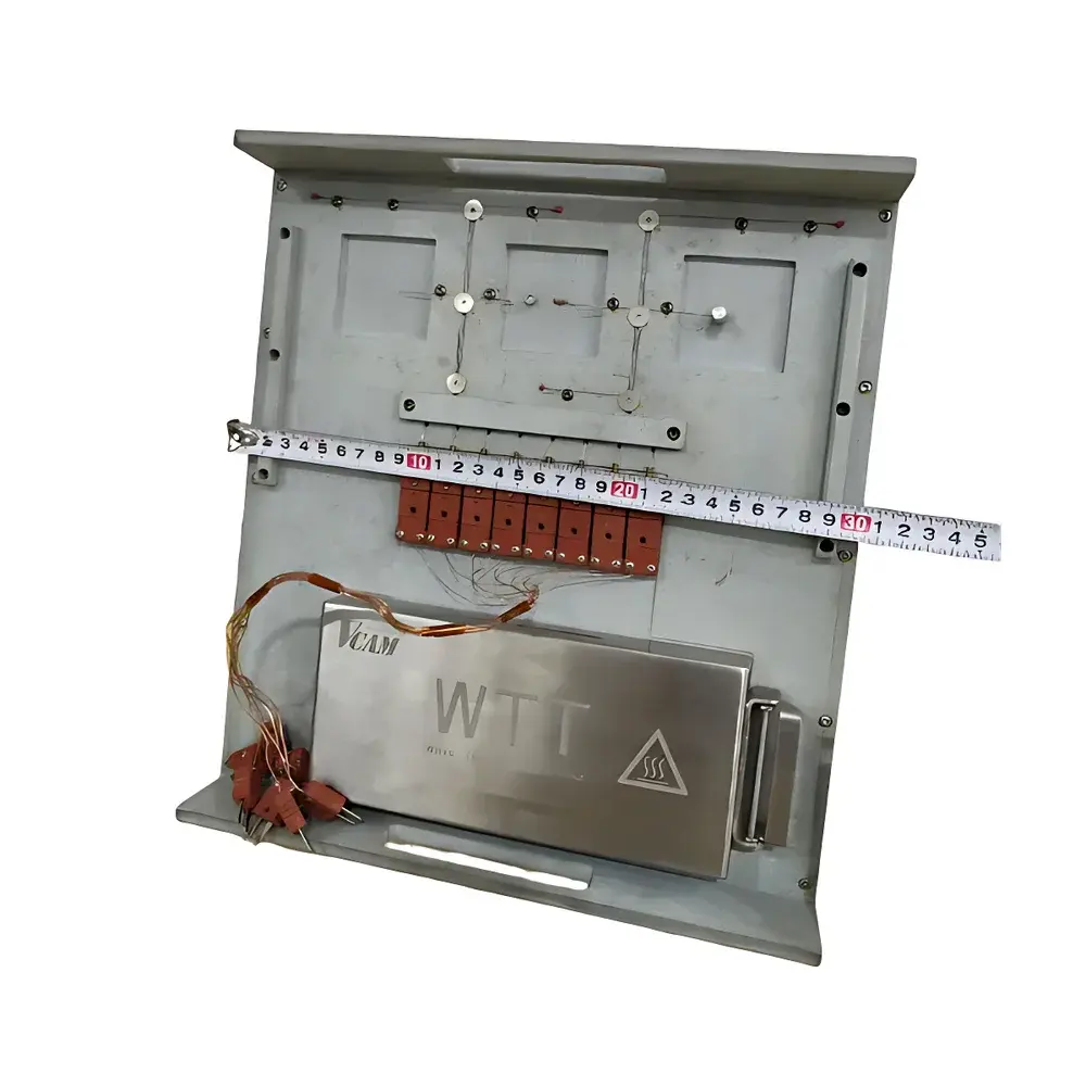
The system accommodates standard photoelastic specimens ranging from 20 × 20 mm to 100 × 100 mm in planar dimension and 3–12 mm in thickness. Compatible materials include optically clear thermoplastics (polycarbonate, PMMA), epoxy resins, and polyurethane gels—each characterized by known stress-optic coefficients (C = 3.5–7.2 × 10⁻¹² Pa⁻¹ for common grades). All optical components meet ISO 10110 surface quality specifications (scratch-dig: 60-40), and the illumination subsystem complies with IEC 62471 Photobiological Safety requirements for Class 1 LED sources. The system supports pedagogical alignment with ASTM E837 (strain gage calibration) and ISO/IEC 17025-compliant laboratory practice frameworks when used with traceable reference standards.
Software & Data Management
Bundled software includes PhotoElastic Studio v3.2—a Windows-based application supporting live fringe capture, temporal sequence export (TIFF/AVI), isochromatic fringe order tracking, and side-by-side comparison with finite element simulation overlays (import via .csv or .vtu). The software implements audit-trail logging per GLP guidelines, records operator ID, timestamp, exposure settings, and calibration history, and exports metadata-enriched reports compatible with LIMS integration. Export formats conform to FAIR data principles (Findable, Accessible, Interoperable, Reusable), including embedded EXIF tags for optical parameters and DICOM-SR-compatible structured reporting for academic documentation.
Applications
- Undergraduate labs: Qualitative demonstration of Saint-Venant’s principle, stress concentration around discontinuities, and dynamic stress shielding effects
- Graduate research: Experimental validation of transient elastodynamic FEM models (e.g., Abaqus Explicit, ANSYS LS-DYNA) under impact or harmonic loading
- Nondestructive evaluation (NDE) training: Visualization of ultrasonic guided wave mode structures in plates and rods
- Materials science instruction: Comparative analysis of viscoelastic damping behavior across polymer formulations using decay envelope measurement
- Interdisciplinary projects: Coupling with digital image correlation (DIC) systems for full-field strain-stress mapping correlation
FAQ
Is this system compatible with third-party ultrasonic transducers?
Yes—the system provides SMA-trigger and BNC-signal output ports supporting industry-standard piezoelectric transducers (e.g., Olympus V301, Panametrics A103-RM) with impedance matching networks.
Can fringe patterns be quantified for stress magnitude estimation?
While primarily designed for qualitative and comparative analysis, fringe order calibration using known-load reference specimens enables semi-quantitative stress mapping within ±12% uncertainty (per ISO/IEC 17025 internal validation protocol).
Does the system support remote operation in hybrid teaching environments?
Yes—software includes TCP/IP API access, allowing integration with LabVIEW, Python (via PySerial), or MATLAB for automated experiment sequencing and cloud-based result aggregation.
What maintenance is required for long-term optical stability?
Annual recalibration of polarizer/analyzer azimuth angles and LED intensity drift compensation is recommended; no consumables or proprietary service contracts are required.