Electromagnetic Vibration and Shock Testing System
| Brand | Other Brands |
|---|---|
| Origin | Imported |
| Manufacturer Type | General Distributor |
| Price | USD 21,000 (approx.) |
Overview
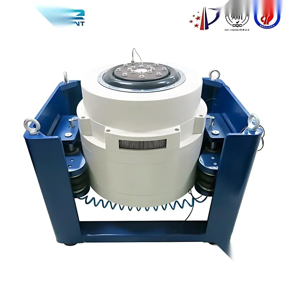
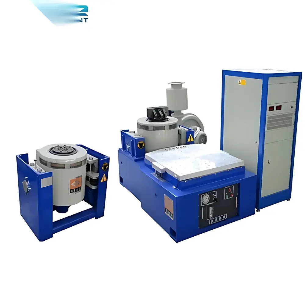
The Electromagnetic Vibration and Shock Testing System is a precision-engineered laboratory-grade shaker system designed to replicate dynamic mechanical stress environments encountered during transportation, operation, and service life of electro-mechanical components, aerospace subsystems, automotive modules, and electronic enclosures. It operates on electromagnetic excitation principles—utilizing voice-coil actuators to generate controlled acceleration profiles across a defined frequency range. Unlike hydraulic or servo-hydraulic shakers, electromagnetic systems offer high linearity, fast response, low harmonic distortion, and excellent repeatability in both sinusoidal and random vibration modes. This system supports two fundamental excitation paradigms: deterministic sinusoidal sweep (for resonance detection, modal analysis, and fatigue threshold identification) and broadband random vibration (for statistical simulation of real-world road, air, or sea transport spectra). Critically, the system does not assume equivalence between sine and random test severity—a principle aligned with ISO 10816, ASTM D999, and MIL-STD-810H guidance, which emphasize mode-specific test rationale rather than amplitude-based conversion.
Key Features
- Programmable multi-segment sweep capability—enabling complex time-varying frequency/amplitude profiles compliant with IEC 60068-2-6 and RTCA DO-160 Section 8 requirements
- Integrated amplitude prediction algorithm with real-time feedback control for precise displacement/acceleration targeting
- Four-point synchronous electromagnetic excitation ensuring uniform force distribution and minimized rocking moment across the vertical shaker table
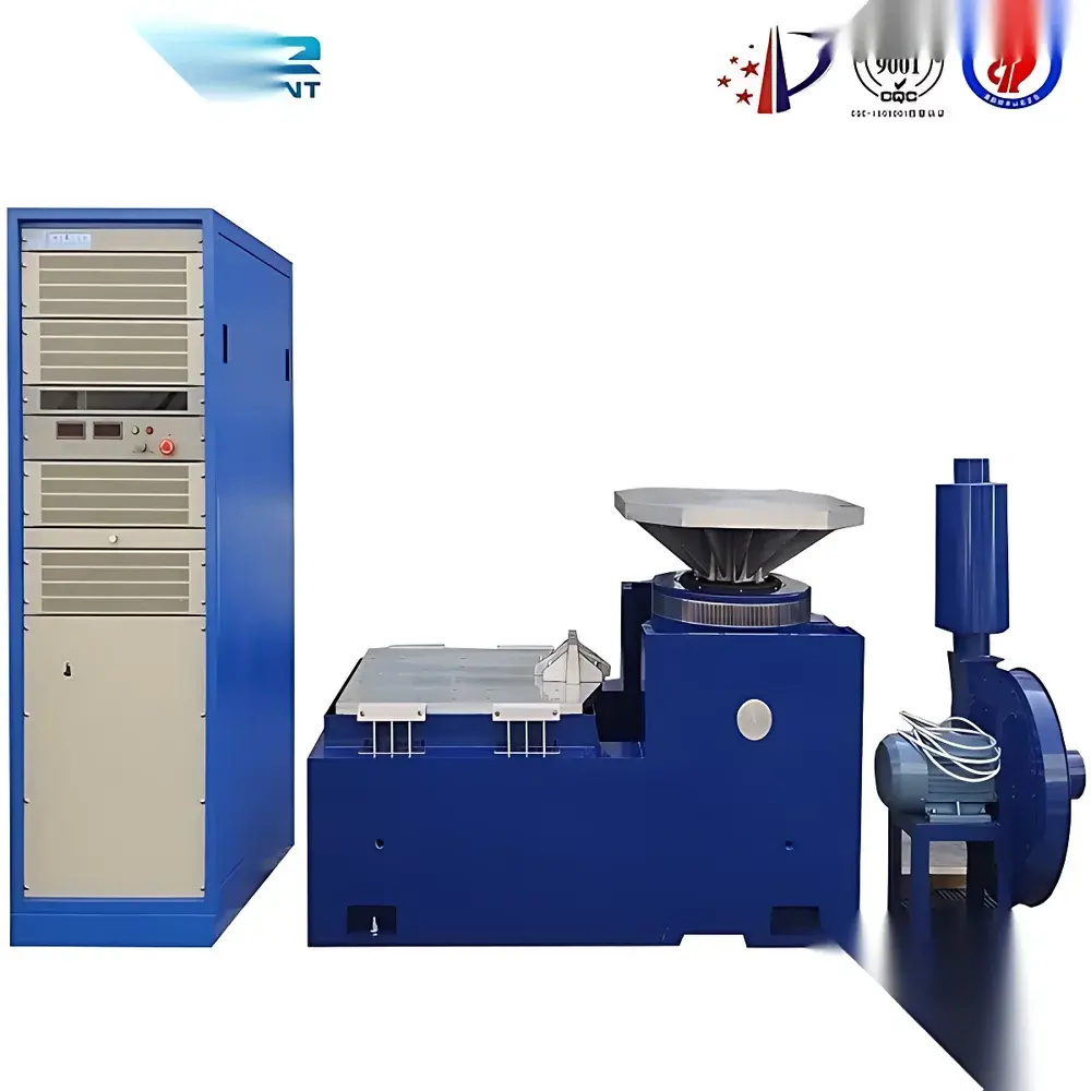
- Digital PID-controlled frequency generator with continuous 5–3000 Hz tuning range (typical), displayed via high-resolution LCD interface
- Onboard timer functions: single-stage, multi-stage, countdown, and elapsed time logging with non-volatile memory retention
- Passive anti-vibration base mount—eliminates need for anchor bolts or reinforced concrete foundations; suitable for standard laboratory flooring
- EMI-hardened control circuitry with shielded signal paths and ferrite-filtered power inputs to maintain stability in electrically noisy test environments
- Stepless amplitude adjustment (displacement ±1 mm to ±76 mm peak-to-peak; acceleration up to 100 gpk, depending on payload and frequency)
Sample Compatibility & Compliance
The system accommodates test specimens up to 100 kg (standard configuration) with mounting interface per ISO 5344 and DIN 45672 standards. Fixture design must comply with modal decoupling best practices to avoid spurious resonance coupling. The platform meets CE marking requirements under the Machinery Directive 2006/42/EC and EMC Directive 2014/30/EU. All control firmware implements audit-trail-capable parameter logging, supporting GLP/GMP traceability when integrated with external data acquisition systems. While not inherently 21 CFR Part 11 compliant, the system’s digital interface allows integration with validated LIMS or QMS platforms for regulated industries including medical device validation (per ISO 13485) and avionics qualification.
Software & Data Management
The embedded controller provides real-time display of acceleration (gpk), velocity (mm/s), displacement (mmpp), frequency (Hz), and phase response. Optional PC-based software enables waveform synthesis (sine, random, shock pulse, SRS synthesis), spectrum editing (PSD shaping), test report generation (PDF/CSV), and live spectral monitoring using FFT-based analysis. Data export conforms to IEEE 1159-compliant metadata tagging, facilitating long-term archival and cross-platform interoperability. All setpoints, limits, and pass/fail criteria are stored with timestamps and user ID—enabling full revision history for internal audits.
Applications
- Resonance search and dwell testing per MIL-STD-810H Method 514.8
- Vibration fatigue screening of PCB assemblies, connectors, and solder joints
- Transport simulation for packaging validation (ASTM D4728, ISTA 3A)
- Modal parameter identification for structural dynamics modeling
- Shock response spectrum (SRS) analysis of pyroshock and impact events
- Qualification testing of inertial sensors, MEMS devices, and optical payloads
FAQ
Can this system perform classical shock testing (e.g., half-sine, trapezoidal pulses)?
Yes—when configured with optional shock amplifier and pulse generator module, it supports programmable transient acceleration profiles per ISO 10326-1 and MIL-STD-810H Method 516.6.
Is remote operation supported?
Standard Ethernet (TCP/IP) and RS-232 interfaces enable SCPI command control and integration into automated test benches via LabVIEW, Python, or MATLAB.
What is the maximum allowable payload eccentricity?
For optimal performance and actuator longevity, center-of-gravity offset should not exceed ±15 mm from the table centerline in any axis.
Does the system include calibration certification?
A factory calibration certificate (traceable to NIST or PTB standards) is provided with initial delivery; annual recalibration is recommended per ISO/IEC 17025 guidelines.
Can random vibration tests be executed with closed-loop control?
Yes—the system employs real-time error minimization using accelerometer feedback and adaptive PSD correction algorithms, maintaining tolerance bands within ±1.5 dB across the specified bandwidth.


