GFM 3D Optical Step Height and Surface Defect Profilometer
| Brand | GFM |
|---|---|
| Country of Origin | Germany |
| Model | 3D Step Height & Surface Defect Profilometer |
| Measurement Principle | Laser Stripe Phase Projection with DSP-Based Real-Time Image Processing |
| Measurement Range (X/Y/Z) | 13 × 8 × 5 mm |
| Measurement Uncertainty | (2 + L/1000) µm (L in µm) |
| Vertical Resolution | 1 µm |
| Working Distance | 107 mm |
| Scan Time per Frame | 3 s |
| Point Cloud Density | 360,000 points/frame |
| Operating Temperature | 5–40 °C |
| Light Source | Blue LED |
| Optical Path | High-Angle Illumination Design |
| Software | Dedicated Scratch & Step Analysis Suite with Polynomial/Gaussian/Mean Filtering |
Overview
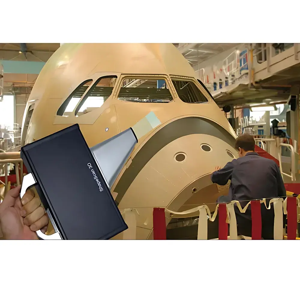
The GFM 3D Optical Step Height and Surface Defect Profilometer is a handheld, field-deployable metrology instrument engineered for non-contact, high-resolution 3D topographic characterization of surface defects and geometric features. It operates on the principle of laser stripe phase projection—where a structured blue LED light pattern is projected onto the target surface, and distortions in the reflected stripe are captured by a high-sensitivity CMOS sensor. Real-time DSP-based triangulation reconstructs the surface topology with sub-micron vertical resolution. Unlike conventional contact profilometers or time-of-flight scanners, this system delivers quantitative depth, step height, and contour data without mechanical scanning or surface interaction—making it ideal for delicate, coated, or high-reflectivity surfaces such as polished metals, carbon-fiber composites, and anodized aerospace alloys. Its compact form factor, integrated battery, and ruggedized housing support in-situ inspection directly on production floors, aircraft fuselages, wind turbine blades, or ship hulls—eliminating the need for sample removal or lab transfer.
Key Features
- Portable, battery-powered design optimized for on-site metrology in constrained or remote environments.
- Blue LED illumination combined with high-angle optical path geometry minimizes specular reflection artifacts on highly reflective or curved surfaces—including mirror-finished stainless steel and titanium alloys.
- Vertical resolution of 1 µm and measurement uncertainty specified as (2 + L/1000) µm ensures traceable, repeatable quantification of step heights, scratch depths, and corrosion pitting—fully compliant with ISO 25178-2 and VDA 262 surface texture reporting requirements.
- Single-frame acquisition time of 3 seconds generates dense point clouds of 360,000 vertices, enabling rapid statistical analysis of defect distribution across large inspection zones.
- Dedicated software includes adaptive filtering algorithms—polynomial fitting for global curvature compensation, Gaussian smoothing for noise suppression, and mean filtering for edge-preserving artifact reduction—critical for isolating true surface features from substrate tilt, dust contamination, or machining-induced waviness.
- Full SDK support enables integration into automated QA workflows, custom reporting systems, or Industry 4.0 MES platforms via TCP/IP or USB-C interfaces.
Sample Compatibility & Compliance
The profilometer is validated for use on conductive and non-conductive materials including aluminum alloys, nickel-based superalloys, CFRP laminates, woven textiles, and elastomeric coatings. Its non-destructive optical method avoids indentation, thermal loading, or electrostatic interference—ensuring integrity of functional surfaces post-inspection. Calibration is traceable to national metrology institutes (e.g., PTB, NIST) in accordance with ISO/IEC 17025 and DIN EN ISO 9001 quality management frameworks. All measurement reports include audit-ready metadata: timestamp, operator ID, environmental conditions (temperature/humidity), calibration certificate reference, and raw point cloud export—supporting GLP-compliant documentation for aerospace (AS9100), automotive (IATF 16949), and medical device (ISO 13485) applications.
Software & Data Management
The bundled GFM SurfaceAnalyzer software provides full 3D visualization, cross-sectional profiling, and ISO 25178-compliant roughness parameter extraction (Sa, Sq, Sdr, etc.). Users can define custom ROI masks, apply multi-scale filtering cascades, and generate color-mapped topography maps where hue encodes elevation (e.g., red = deepest scratch, blue = reference plane). Export formats include ASCII XYZ, STL, CSV, and industry-standard STEP AP214 for CAD comparison. Audit trails record all user actions—including filter selections, threshold adjustments, and report generation—with optional 21 CFR Part 11 compliance mode (electronic signatures, role-based access, immutable logs) available upon configuration.
Applications
- Aerospace: Quantifying rivet head flushness, weld bead undercut, fastener hole countersink depth, and FOD-induced surface damage on wing skins or engine casings.
- Automotive: Measuring paint chip depth, brake rotor scoring, gasket interface step heights, and composite panel bond line uniformity.
- Power Generation: Assessing erosion/corrosion profiles on turbine blades, heat exchanger tubes, and nuclear fuel cladding surfaces.
- Electronics Manufacturing: Verifying solder joint coplanarity, PCB pad wear, and micro-connector mating surface flatness.
- Research & Development: Correlating surface topography with fatigue initiation sites, tribological wear mechanisms, or coating adhesion failure modes.
FAQ
Is the instrument suitable for measuring scratches on highly polished chrome-plated surfaces?
Yes—the blue LED illumination and oblique optical path suppress specular glare, enabling stable fringe capture even on mirror-like finishes.
Can measurement data be exported for statistical process control (SPC) analysis?
Yes—CSV exports include X/Y/Z coordinates, calculated depth values, and statistical summaries (mean, std dev, max/min) compatible with Minitab, JMP, and Python-based SPC libraries.
Does the system require periodic recalibration by the manufacturer?
No—users perform daily verification using certified step-height reference standards; full calibration is recommended annually or after impact events, traceable to accredited labs.
What is the maximum allowable surface curvature for accurate measurement?
The system maintains <1% deviation up to ±15° local surface slope; beyond that, polynomial tilt correction in software compensates for macro-curvature effects.
Is the SDK compatible with LabVIEW and MATLAB?
Yes—native drivers and example scripts are provided for both environments, supporting real-time streaming, batch acquisition, and automated pass/fail decision logic.


