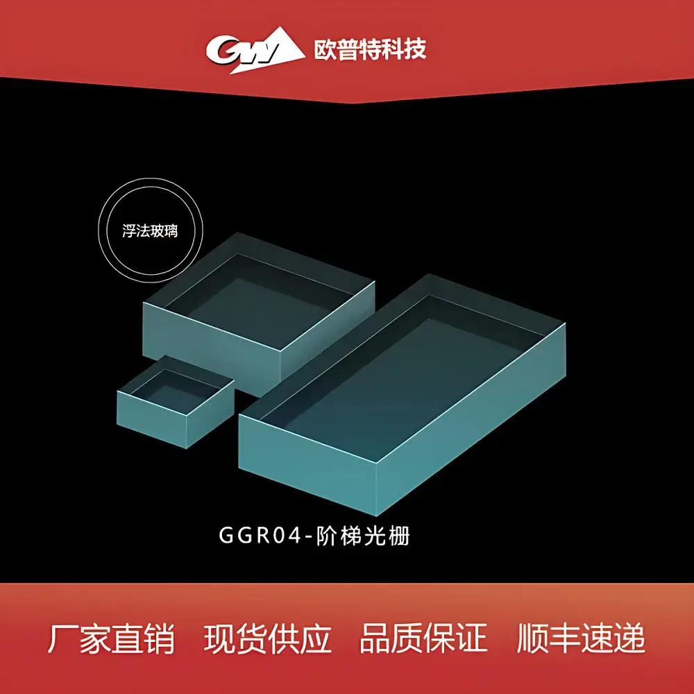
GGR04 Step Diffraction Grating
| Origin | Beijing, China |
|---|---|
| Manufacturer Type | Authorized Distributor |
| Product Category | Optical Component |
| Model | GGR04 |
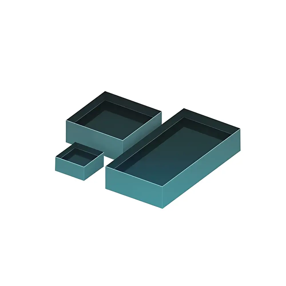
| Dimensions (L×W×H) | 12.5×25×9.5 mm / 25×50×9.5 mm / 50×50×9.5 mm |
| Groove Density | 31.6, 79, or 316 lines/mm |
| Blaze Wavelength | UV–5.7 µm (depending on configuration) |
| Blaze Angle | 63° or 75° |
| Angular Dispersion | 14.37–1.44 nm/mrad |
| Part Numbers | GGR04-1313-XXX, GGR04-2525-XXX, GGR04-2550-XXX (where XXX encodes groove density and blaze angle) |
Overview
The GGR04 Step Diffraction Grating is a precision-engineered ruled optical grating component designed for high-efficiency spectral dispersion in laboratory-grade and OEM-integrated optical systems. Fabricated using advanced diamond ruling techniques on optically polished substrates (typically BK7 or fused silica), the GGR04 employs a step-profile (blazed) groove geometry to maximize diffraction efficiency into a single order—particularly at its designated blaze wavelength. Its operating principle relies on constructive interference of light waves reflected from regularly spaced, angled grooves, enabling precise angular separation of polychromatic light according to wavelength (governed by the grating equation: mλ = d(sinα + sinβ)). This makes it suitable for applications requiring deterministic spectral resolution in compact optical paths, including monochromators, spectrographs, laser pulse compressors, and wavelength calibration references.
Key Features
- Multiple standard substrate dimensions: 12.5 × 25 × 9.5 mm, 25 × 50 × 9.5 mm, and 50 × 50 × 9.5 mm—optimized for integration into modular spectrometer benches and custom optical mounts.
- Selectable groove densities: 31.6, 79, and 316 lines/mm—enabling trade-offs between spectral resolution, free spectral range (FSR), and angular dispersion across UV, visible, and near-IR bands.
- Two standard blaze angles: 63° and 75°—engineered to align peak diffraction efficiency with specific spectral regions (e.g., 63° for broad UV–VIS coverage; 75° for enhanced performance in UV-dominated applications).
- High surface quality: λ/10 surface flatness and ≤5 Å RMS roughness ensure minimal wavefront distortion and scatter-induced signal loss.
- Robust coating options: Available uncoated, Al+MgF₂ (UV-enhanced reflectivity), or protected silver (broadband VIS–NIR), all deposited under controlled vacuum conditions and verified via spectrophotometric reflectance mapping.
- Traceable part numbering system (e.g., GGR04-2550-7975): Encodes dimensional format, groove density (79 l/mm), and blaze angle (75°), supporting configuration control and repeatable procurement in regulated environments.
Sample Compatibility & Compliance
The GGR04 is compatible with collimated beam illumination over ±2° incident angle tolerance and supports input beam diameters up to 80% of clear aperture. It meets ISO 10110-7 standards for surface imperfections and groove uniformity (groove spacing error ≤ ±0.2% across aperture). While not an end-use instrument itself, the grating is routinely deployed in systems subject to IEC 61000-6-3 (EMC), ISO/IEC 17025 (calibration lab traceability), and FDA 21 CFR Part 11-compliant analytical platforms—provided the host instrument implements appropriate audit trails and calibration documentation. No hazardous substances are used in manufacturing; RoHS 3 and REACH compliance are certified per batch.
Software & Data Management
As a passive optical component, the GGR04 requires no embedded firmware or driver software. However, its performance parameters—including blaze efficiency curves, polarization-dependent loss (PDL), and Littrow alignment angles—are supplied in machine-readable CSV and NIST-traceable SDF (Spectral Data Format) files upon request. These datasets integrate seamlessly with optical design suites such as Zemax OpticStudio, CODE V, and FRED for ray tracing, stray light analysis, and system-level sensitivity modeling. For quality assurance, each shipment includes a Certificate of Conformance listing measured groove density (via interferometric verification), surface flatness (Fizeau interferometry), and reflectance spectra (PerkinElmer Lambda 1050+).
Applications
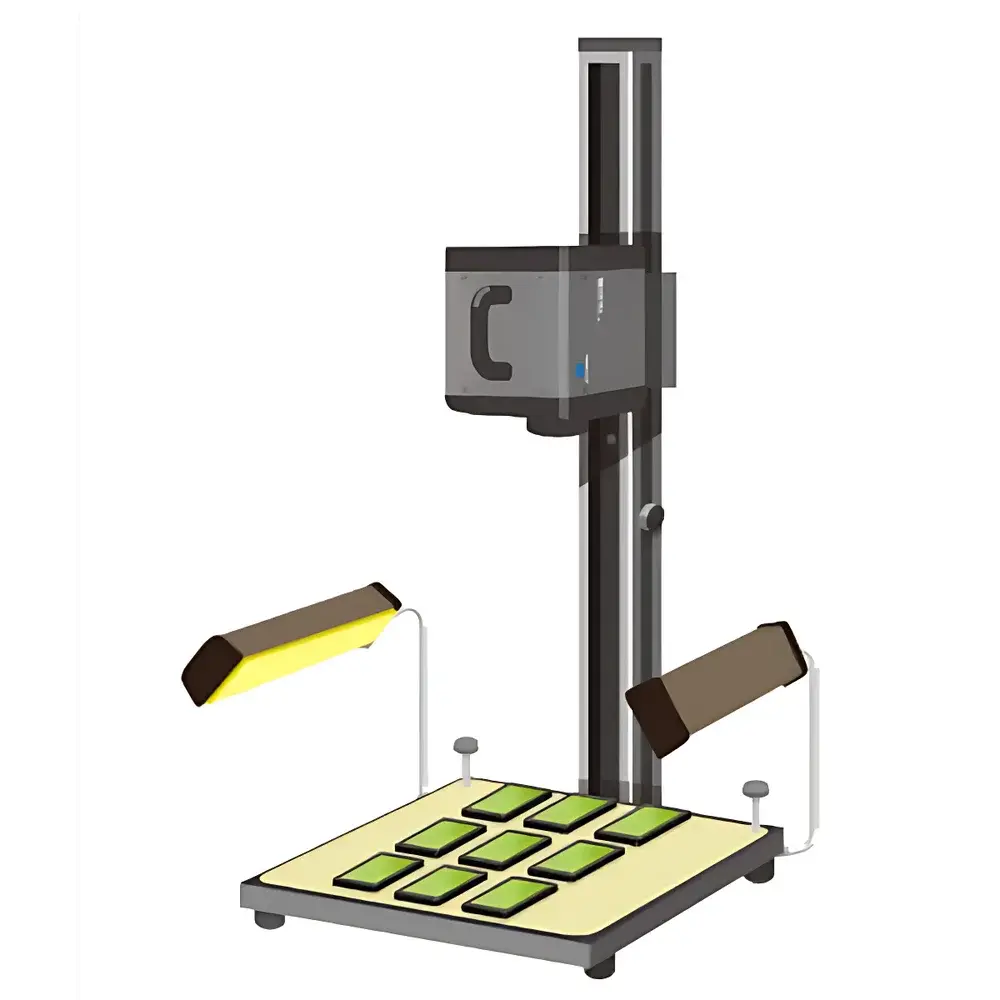
- Spectroscopic instrumentation: Core dispersive element in benchtop UV-VIS-NIR spectrophotometers (e.g., replacements for legacy gratings in Shimadzu UV-2600 or Agilent Cary 60 systems).
- Laser systems: Pulse stretcher/compressor gratings in Ti:sapphire CPA architectures; line selection elements in external cavity diode lasers (ECDLs).
- Biochemical analyzers: Wavelength selection in fluorescence microplate readers and flow cytometry excitation modules.
- Calibration standards: Reference grating for wavelength validation of CCD- and CMOS-based spectrometers per ASTM E275 and ISO 13406-2 protocols.
- Academic research: Teaching optics labs (interference/diffraction experiments), Fourier-transform spectroscopy test benches, and hyperspectral imaging prototype development.
FAQ
What is the difference between a step (blazed) grating and a holographic grating?
A step grating features triangularly profiled grooves machined via mechanical ruling, yielding high first-order efficiency at a specific blaze wavelength. Holographic gratings use interference lithography to produce sinusoidal grooves, offering lower stray light but broader, less peaked efficiency curves.
Can the GGR04 be used in vacuum or UHV environments?
Yes—when fabricated on low-outgassing fused silica substrates and without organic adhesives, the GGR04 is compatible with UHV systems (<10⁻⁹ mbar); bake-out stability up to 150°C is verified for Al+MgF₂ coatings.
Is groove density uniform across the entire aperture?
Yes—groove density variation is maintained within ±0.15 lines/mm across the full clear aperture, confirmed by automated scanning white-light interferometry.
How is blaze efficiency measured and reported?
Absolute diffraction efficiency is measured at 10 nm intervals from 200–1100 nm using a calibrated double-monochromator setup traceable to NIST SRM 2036, with results provided in the CoC.
Do you offer custom groove profiles or non-standard substrates?
Yes—custom rulings (e.g., asymmetric blazes, concave substrates, or CaF₂ for deep-UV) are available under NDA with lead times of 8–12 weeks and MOQ of 5 units.