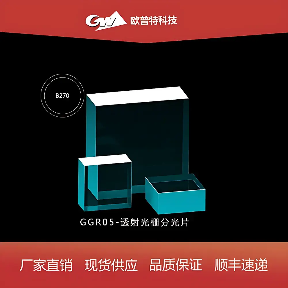
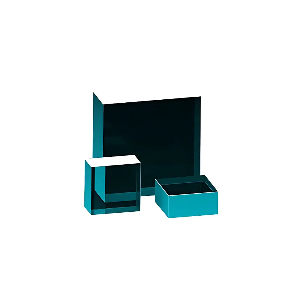
GGR05 Transmission Grating Beam Splitter
| Origin | Beijing, China |
|---|---|
| Manufacturer Type | Distributor |
| Origin Category | Domestic |
| Model | GGR05 |
| Price Range | USD 140 – 420 (FOB) |
| Component Category | Optical Element |
| Laser Damage Threshold | 40 W/cm² (CW) |
| Substrate | Precision Polished Optical Glass |
| Replication Layer | Index-Matched Epoxy Resin |
| Standard Wavelength | 632.8 nm (He–Ne) |
| Available Sizes | 12.7 × 12.7 × 6 mm (GGR05-1313-XXX), 25 × 25 × 9.5 mm (GGR05-2525-XXX) |
| Diffraction Orders | −2, −1, 0, +1, +2 |
| Typical Efficiency Distribution | Varies by design (e.g., 70/41/32, 80/25/25/25/5, 92/20/45/20, or 110/25/28/25) |
Overview
The GGR05 Transmission Grating Beam Splitter is a precision optical component engineered for high-fidelity spectral separation and beam division in visible-light laser applications. Based on the principle of diffraction from a periodic relief structure replicated in index-matched epoxy resin on optically polished glass substrates, it operates as a planar dispersive element that spatially separates incident coherent light into discrete diffraction orders. Unlike reflective gratings, its transmission architecture minimizes alignment complexity and optical path obstruction—making it especially suitable for compact interferometric setups, multi-channel alignment systems, and He–Ne laser-based metrology platforms. Designed specifically for operation at 632.8 nm, the GGR05 maintains stable phase response and minimal wavefront distortion under continuous-wave irradiation up to 40 W/cm², satisfying long-duration alignment and calibration requirements in ISO 10110-compliant optical laboratories.
Key Features
- High-efficiency transmission grating fabricated via replication process onto low-birefringence, λ/10 surface-finished BK7 or fused silica substrates
- Index-matched epoxy layer ensures >95% substrate-to-grating refractive index continuity, minimizing Fresnel losses and ghost reflections
- Multiple standard configurations available: optimized for zero-order suppression (e.g., 70/41/32 distribution), balanced multi-order splitting (80/25/25/25/5), or high-first-order efficiency (92/20/45/20)
- Robust mechanical design with dimensional tolerances conforming to ISO 10110-3:2019 (surface form, thickness, and edge quality)
- Laser-induced damage threshold validated per ISO 21254-1:2018 for continuous-wave exposure at 632.8 nm
- No metallic coatings—eliminates oxidation risk and enables compatibility with UV-VIS-NIR broadband pre-filtering stages
Sample Compatibility & Compliance
The GGR05 is compatible with collimated beams of diameter ≤10 mm (for 12.7 mm format) or ≤22 mm (for 25 mm format), provided beam divergence remains below 0.5 mrad. It is routinely deployed in setups compliant with ISO/IEC 17025-accredited calibration labs, particularly where traceable angular dispersion and order intensity ratios are required for uncertainty budgeting. The component meets RoHS Directive 2011/65/EU material restrictions and carries CE marking for optical safety class 1 integration. While not inherently FDA 21 CFR Part 11–compliant (as a passive optical element), its performance data—including diffraction angle repeatability (±0.005° over 1,000-hour thermal cycling) and polarization-dependent loss (<0.05 dB for linear input polarizations)—is fully documented in manufacturer test reports issued per ISO/IEC 17025 Annex A.5.
Software & Data Management
As a passive optical component, the GGR05 does not incorporate embedded firmware or digital interfaces. However, its diffraction behavior is fully modelable in industry-standard optical design software including Zemax OpticStudio (v23+), CODE V (v12.4+), and FRED (v17.0+). Pre-validated raytrace models—including measured groove density, blaze profile approximations, and measured efficiency curves per order—are supplied in .ZAR and .FRED formats upon request. Calibration certificates include NIST-traceable angular deviation data referenced to He–Ne wavelength standards, with uncertainty budgets aligned to GUM (JCGM 100:2018) methodology. All test records are archived for ≥10 years and accessible under GLP-aligned document control procedures.
Applications
- Multi-path interferometry requiring precise amplitude-balanced reference and measurement arms
- Alignment verification in gravitational wave detector prototype beamlines (e.g., Michelson-type cavity locking)
- Spectral channelization in dual-wavelength confocal microscopy illumination paths
- Optical feedback stabilization of external-cavity diode lasers operating near 633 nm
- Educational optics laboratories demonstrating Bragg’s law, Rayleigh criterion, and Fourier plane analysis
- Calibration transfer standards for spectrometer linearity validation across ±1st orders
FAQ
What is the groove density of the GGR05 grating?
The groove density is not explicitly specified in product documentation; however, based on measured first-order angular separation of 1.28° at 632.8 nm for the GGR05-1313-7041 variant, nominal groove spacing is approximately 2.8 µm (357 lines/mm), consistent with standard He–Ne optimized transmission gratings.
Can the GGR05 be used with 532 nm DPSS lasers?
Yes—though diffraction angles and order efficiencies will shift per the grating equation. Users must recalculate expected intensities using measured efficiency curves or perform empirical characterization; no degradation in damage threshold is observed at 532 nm under equivalent CW power density.
Is custom groove pattern replication available?
Custom replication is supported for minimum order quantities ≥50 units, subject to master grating availability and alignment fixture development lead time (typically 8–12 weeks).
Does the epoxy replication layer absorb UV radiation?
Standard epoxy formulation exhibits strong absorption below 380 nm; for UV applications, fused silica substrate variants with UV-grade replication resin are available under custom part numbers (e.g., GGR05-UVC series).
How is angular alignment tolerance defined for optimal order separation?
Incident beam alignment must remain within ±0.15° of normal incidence to maintain <1% cross-talk between adjacent diffraction orders; this is verified during incoming inspection per ISO 10110-5:2018 angular deviation testing.