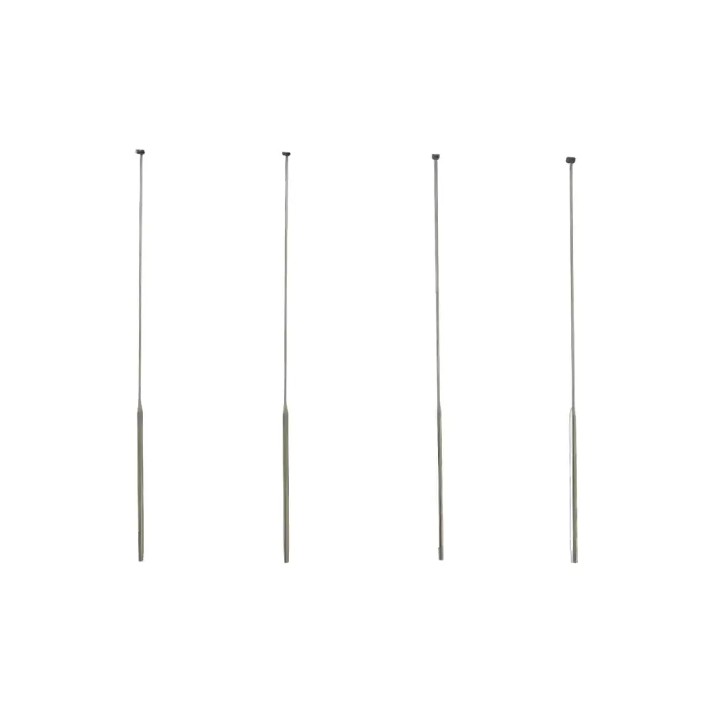
GKinst GK-BSD Series X-ray Beam Stop
| Brand | GKinst |
|---|---|
| Model | GK-BSD Series |
| Material | Cu-Pb Composite |
| Diameter Range | 1.5–10 mm |
| Rod Diameter | 4 mm |
| Rod Length | 200 mm (customizable) |
| Compliance | ISO 17025-aligned installation practices |
| Mounting | Standard M4 threaded stem |
| Radiation Attenuation | Optimized for Cu Kα (8.04 keV) and Mo Kα (17.48 keV) X-ray sources |
Overview
The GKinst GK-BSD Series X-ray Beam Stop is a precision-engineered collimation and radiation shielding component designed for integration into laboratory-scale X-ray diffraction (XRD), small-angle X-ray scattering (SAXS), and X-ray reflectometry (XRR) systems. Its primary function is to intercept the unscattered, high-intensity primary X-ray beam—commonly referred to as the “direct beam” or “zero-order beam”—before it reaches the area detector or point detector. By physically blocking this intense central beam, the GK-BSD prevents detector saturation, pixel bleeding, sensor degradation, and long-term damage to charge-coupled device (CCD), hybrid photon counting (HPC), or CMOS-based detectors. Constructed from a layered copper–lead (Cu-Pb) composite, the beam stop leverages the complementary attenuation properties of both metals: copper provides effective absorption at lower-energy X-ray wavelengths (e.g., Cu Kα at 1.54 Å), while lead ensures robust attenuation across higher-energy ranges (e.g., Mo Kα at 0.71 Å). This dual-material architecture enables consistent performance across diverse source configurations without requiring recalibration or replacement when switching between anode materials.
Key Features
- Precision-machined Cu-Pb composite construction with controlled layer thicknesses for balanced attenuation and minimal scatter generation
- Standardized M4 external thread for secure, repeatable mounting on goniometer arms, detector stages, or custom kinematic mounts
- Diameter options spanning 1.5 mm to 10.0 mm in 0.5 mm increments—enabling precise alignment with beam divergence, sample-to-detector distance, and detector active area geometry
- Fixed 4 mm-diameter support rod (200 mm length) with optional customization for extended reach or alternative threading (M3, M5, or metric/Imperial UNC variants)
- Surface-finished to minimize parasitic scattering; all edges deburred and radiused per ISO 13715 standards for metrological reliability
- Compatible with vacuum-compatible and inert-atmosphere XRD chambers via optional stainless-steel housing upgrades
Sample Compatibility & Compliance
The GK-BSD series is intended for use in non-destructive, solid-state structural characterization workflows. It does not contact samples directly and imposes no constraints on sample composition, phase, or environment (ambient, He-purged, humidity-controlled, or cryogenic). Its mechanical design adheres to widely adopted mechanical interface conventions in commercial diffractometers (e.g., Bruker D8, Rigaku SmartLab, PANalytical Empyrean). While the beam stop itself is not a measuring instrument—and therefore not subject to calibration certification under ISO/IEC 17025—it is engineered to support measurement integrity in accordance with ISO 21363 (X-ray diffraction — General requirements for the use of reference materials) and ASTM E975 (Standard Practice for X-ray Diffraction Crystallographic Analysis). Users deploying GK-BSD in regulated environments (e.g., pharmaceutical QC labs operating under FDA 21 CFR Part 11 or ICH Q5E) are advised to document installation, positioning verification (via laser alignment or pinhole imaging), and periodic visual inspection as part of their equipment qualification (IQ/OQ) protocols.
Software & Data Management
The GK-BSD operates as a passive hardware component and requires no firmware, drivers, or software integration. However, its correct placement is critical for downstream data fidelity. Modern XRD acquisition software—including Bruker DIFFRAC.SUITE, PANalytical HighScore Plus, and open-source packages such as pyFAI and Dioptas—relies on accurate beam center coordinates during 2D image integration. Misalignment or undersizing of the beam stop results in incomplete beam masking, leading to azimuthal intensity distortion, erroneous background subtraction, and compromised peak shape analysis. GKinst provides a downloadable Beam Stop Alignment Guide (PDF), which includes step-by-step instructions for verifying optical centering using a low-flux test exposure and centroid analysis. All GK-BSD units ship with a traceable dimensional certificate indicating nominal diameter tolerance (±0.02 mm) and rod concentricity (≤0.05 mm TIR), supporting GLP-compliant instrument logbook entries.
Applications
- Primary beam masking in Bragg–Brentano θ–2θ XRD for crystalline phase identification and quantitative Rietveld refinement
- Zero-order suppression in transmission-mode SAXS experiments on polymers, proteins, and nanomaterials
- Background reduction in grazing-incidence XRD (GIXRD) of thin films and multilayer stacks
- Beam conditioning in time-resolved XRD setups where detector dynamic range must be preserved across rapid sequential exposures
- Shielding augmentation in synchrotron beamline end-stations where secondary scattering from upstream optics must be minimized
FAQ
Is the GK-BSD compatible with my existing diffractometer?
Yes—provided your system uses standard M4-threaded beam stop mounts or accepts adapter sleeves. Compatibility has been verified with Bruker, Rigaku, PANalytical, and STOE platforms.
Can I request a custom diameter or rod length?
Yes. GKinst offers OEM customization including non-standard diameters (e.g., 12.7 mm for legacy systems), extended rods (up to 500 mm), and alternative mounting threads (M3, M5, ¼”-28 UNC). Lead time is typically 2–3 weeks.
Does the Cu-Pb material generate fluorescence under X-ray irradiation?
Copper fluorescence (Kα at 8.04 keV) may occur under Mo-source excitation but is effectively absorbed by the adjacent Pb layer. Measured stray signal contribution is <0.03% of incident intensity in validated configurations.
How often should the beam stop be inspected or replaced?
No scheduled replacement is required. Visual inspection for surface pitting or deformation is recommended after every 500 hours of operation at maximum tube power (≥45 kV / 40 mA).
Do you provide installation support or alignment verification services?
Yes. GKinst offers remote alignment assistance via video call and supplies a free MATLAB/Python script for centroid-based beam center validation using raw detector images.