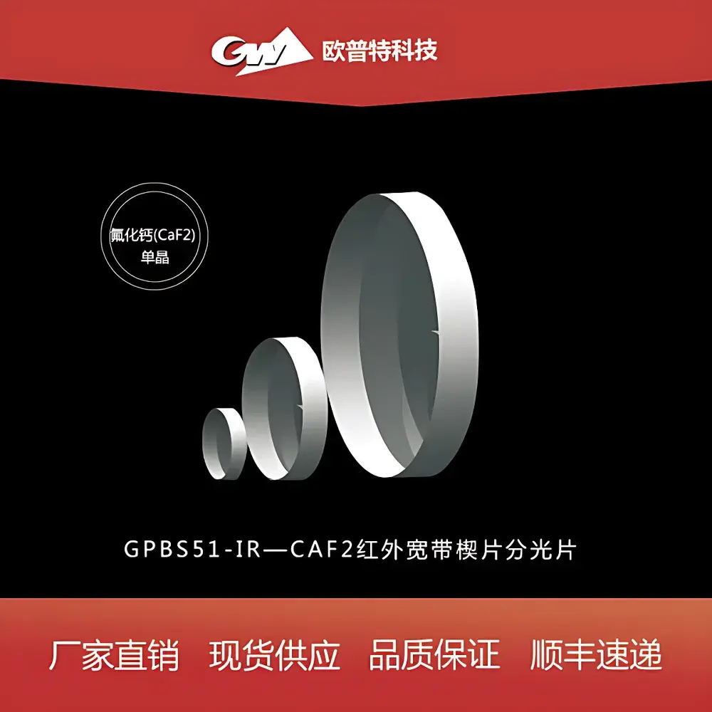
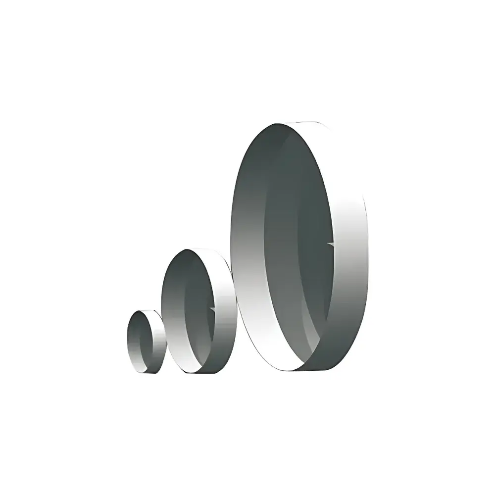
GPBS51 Calcium Fluoride (CaF₂) Infrared Broadband Wedge Beam Splitter
| Material | CaF₂ single crystal |
|---|---|
| Wedge angle | 30 arcmin ± 10 arcmin |
| Surface figure | λ/4 @ 633 nm |
| Surface quality | 3–4 scratch-dig |
| Clear aperture | ≥90% |
| Diameter tolerance | +0/−0.25 mm |
| Thickness tolerance (edge) | ±0.25 mm |
| Edge treatment | Protective chamfer 0.2–0.5 mm × 45° |
| Coating on S1 | Broadband beam-splitting coating for 45° incidence, R/T = 50/50 ±10% avg. over 2–8 µm |
| Coating on S2 | AR coating optimized for 2–8 µm (unspecified reflectance, standard broadband antireflection) |
| Dimensions (Φ × T) | Φ12.7 mm × 3.0 mm, Φ25.4 mm × 5.0 mm, Φ50.8 mm × 8.0 mm |
Overview
The GPBS51 Calcium Fluoride (CaF₂) Infrared Broadband Wedge Beam Splitter is a precision optical component engineered for stable, low-distortion beam division in mid-wave to long-wave infrared (MWIR–LWIR) systems operating from 2 to 8 µm. Unlike flat plate beam splitters, the wedge geometry—defined by a precise 30 arcminute angular deviation between input and output faces—eliminates interference fringes caused by parasitic etalon effects between parallel surfaces. This design ensures high wavefront fidelity and minimizes ghost image formation, making the GPBS51 especially suitable for interferometric setups, FTIR spectrometers, laser cavity dumping, and thermal imaging calibration paths where phase integrity and polarization stability are critical. Fabricated from high-purity, low-absorption CaF₂ single crystal, the wedge exhibits exceptional transmission (>92% per surface uncoated, >95% with AR coating), negligible birefringence, and superior resistance to thermal shock compared to ZnSe or Ge substrates—enabling reliable performance under variable ambient conditions and moderate power densities.
Key Features
- Precision-wedged CaF₂ substrate with surface figure ≤ λ/4 @ 633 nm, verified via interferometric testing to ensure minimal wavefront distortion across the operational IR band.
- Broadband dielectric beam-splitting coating on S1 (front face) designed for 45° angle of incidence, delivering nominal 50R/50T splitting ratio with ±10% uniformity across 2–8 µm—validated via FTIR spectrophotometry.
- Optimized broadband antireflection (BBAR) coating on S2 (rear face), reducing residual reflection to <0.5% per surface across the same spectral range, thereby suppressing secondary reflections and ghost beams.
- Controlled edge geometry: protective 45° chamfer (0.2–0.5 mm) applied to all perimeters to prevent chipping during handling and mounting while maintaining mechanical robustness.
- Clear aperture ≥90% of nominal diameter, with strict dimensional tolerances (+0/−0.25 mm on diameter, ±0.25 mm on edge thickness) to support repeatable integration into kinematic mounts and lens tubes.
- Available in three standardized configurations: Φ12.7 × 3.0 mm, Φ25.4 × 5.0 mm, and Φ50.8 × 8.0 mm—each identified by unique part numbering (e.g., GPBS51-025-50-IR) for traceability and system documentation compliance.
Sample Compatibility & Compliance
The GPBS51 is compatible with standard optomechanical interfaces including SM-threaded lens tubes, kinematic mirror mounts, and breadboard-compatible post holders. Its CaF₂ substrate meets ASTM F263–22 specifications for optical calcium fluoride and conforms to ISO 10110–7 for surface imperfections (scratch-dig grade 3–4). The coatings are deposited via ion-assisted e-beam evaporation, ensuring adhesion durability per MIL-C-48497A and environmental stability under Class 1000 cleanroom handling. While not inherently certified for medical or aerospace use, the component supports GLP-aligned optical alignment workflows and is routinely deployed in ISO/IEC 17025-accredited spectroscopy labs where material traceability and batch-specific test reports are maintained upon request.
Software & Data Management
No embedded firmware or proprietary software is associated with the GPBS51, as it is a passive optical element. However, its spectral performance data—including measured R/T curves, phase retardation profiles, and polarization-dependent loss (PDL) maps—are supplied in CSV and MATLAB-compatible .mat formats upon order fulfillment. These datasets integrate directly into optical design platforms such as Zemax OpticStudio and CODE V for tolerance analysis, stray light modeling, and system-level throughput prediction. All delivered units include a Certificate of Conformance listing substrate lot number, coating deposition date, and interferometric surface verification results—supporting audit readiness under FDA 21 CFR Part 11 when used within regulated analytical instrumentation.
Applications
- FTIR spectrometer reference arms requiring zero-path-difference stability and minimal dispersion-induced phase error.
- MWIR/LWIR laser diagnostics, including cavity-dumped OPOs and quantum cascade laser (QCL) beam sampling at non-destructive power levels.
- Thermal imaging collimation and calibration subassemblies where chromatic aberration must be minimized across broad spectral bands.
- Interferometric gas sensing cells where beam path symmetry and temporal coherence preservation are essential for ppm-level detection limits.
- Multi-spectral radiometric calibration sources utilizing dual-detector architectures with matched optical path lengths.
FAQ
What is the primary advantage of a wedge beam splitter over a flat plate design?
The wedge geometry eliminates coherent interference between front- and back-surface reflections, preventing etalon fringes that degrade signal-to-noise ratio in interferometric and high-resolution spectroscopic applications.
Is the GPBS51 suitable for high-power CO₂ laser applications (10.6 µm)?
No—CaF₂ exhibits increased absorption beyond 8 µm; for 10.6 µm operation, ZnSe or GaAs substrates with appropriate wedge designs are recommended.
Can custom wedge angles or coating ratios be provided?
Yes—custom wedge angles from 15 to 60 arcmin and R/T ratios (e.g., 70/30, 90/10) are available under OEM agreements, subject to minimum order quantities and extended lead times.
How is surface cleanliness validated prior to shipment?
Each unit undergoes white-light interferometry for surface figure, spectral photometry for coating performance, and dark-field microscopy for scratch-dig assessment—all documented in the CoC.
Does the BBAR coating on S2 cover the entire rear surface, including the chamfered edge?
Coating coverage includes the functional clear aperture and extends marginally onto the chamfer; however, the chamfer’s beveled geometry inherently reduces coating stress and improves edge adhesion reliability.