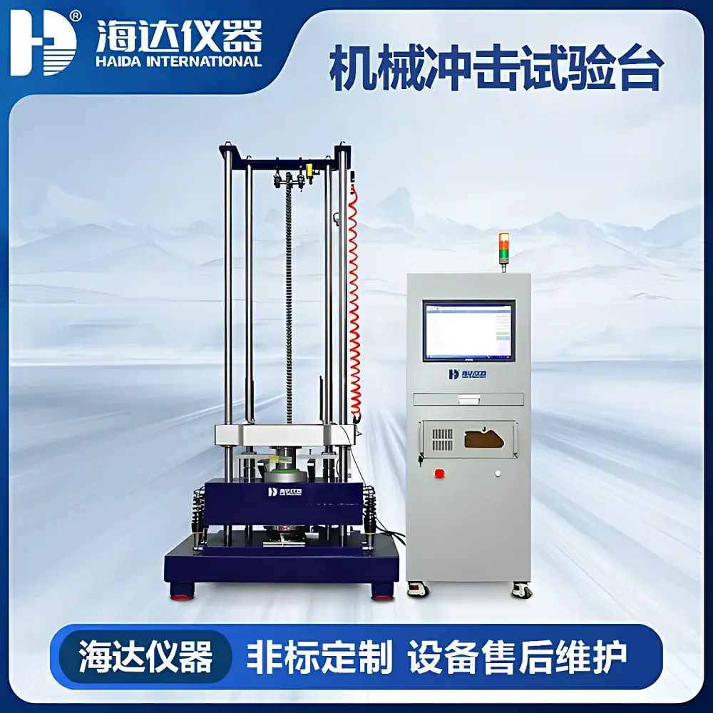
HAIDA HD-G829 Mechanical Shock Test System
| Brand | HAIDA INTERNATIONAL |
|---|---|
| Origin | Guangdong, China |
| Manufacturer Type | Direct Manufacturer |
| Product Category | Domestic |
| Model | HAIDA HD-G829 Mechanical Shock Test System |
| Instrument Type | Mechanical Shock Tester |
| Rated Thrust | 25 kgf |
| Rated Power | 1500 W |
| Maximum Test Load | 25 kg |
| Table Dimensions (L×W×H) | ≈1100 mm × 800 mm × 2500 mm |
| Peak Acceleration Range | 20–1500 g |
| Motor | 750 W Three-Phase Induction Motor |
| Control Method | PC-Based Control |
| Drop Height Range | 0–1500 mm |
| Test Table Surface | 350 mm × 350 mm |
| Table Material | High-Strength Anodized Aluminum Alloy |
| Accelerometer Range | ±2500 g |
| Pulse Duration | 0.5–30 ms |
| Input Channels | 2 |
| Sampling Rate | 192 kHz |
| Input Types | Voltage / Charge |
| Voltage Range | –10 V to +10 V |
| Coupling Modes | AC / DC / ICP |
| Shock Waveform | Half-Sine |
| Communication Interface | USB 2.0 |
| Compliance Standards | GB/T 2423–2019, GJB 150, GJB 360, GJB 548, GJB 1217, MIL-STD-202F, IEC 60068-2-27, MIL-STD-810F, MIL-STD-883E |
Overview
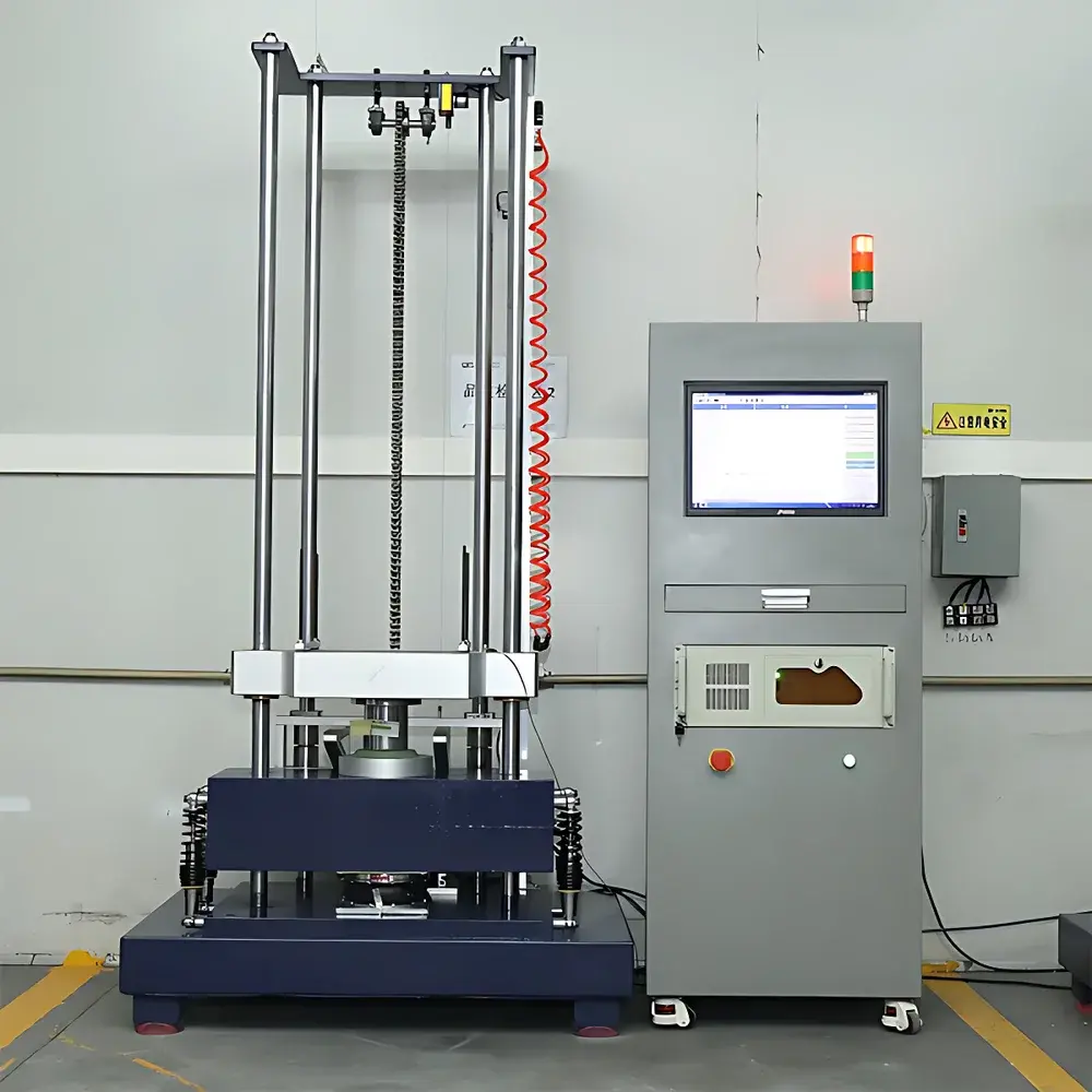
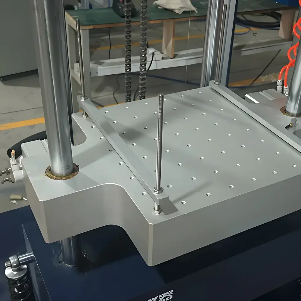
The HAIDA HD-G829 Mechanical Shock Test System is a precision-engineered free-fall shock tester designed for rigorous evaluation of mechanical robustness in components and assemblies subjected to transient high-g acceleration events. Operating on the principle of controlled gravitational drop impact, the system generates repeatable half-sine shock pulses by releasing test specimens from programmable heights onto a calibrated impact surface. Unlike electrodynamic shakers optimized for vibration fatigue, this mechanical shock platform delivers high-energy, short-duration impulses—critical for validating structural integrity under real-world transport, handling, and operational shock conditions. Its architecture integrates a rigid four-column steel frame with a solid base plate to minimize energy dissipation and ensure waveform fidelity. The system is explicitly engineered for laboratories requiring traceable, standards-compliant shock testing across aerospace, defense, automotive electronics, and industrial IoT device development.
Key Features
- Four-column heavy-duty structural design with solid steel base foundation ensures minimal frame resonance and high repeatability (±0.5% pulse-to-pulse variation under identical settings).
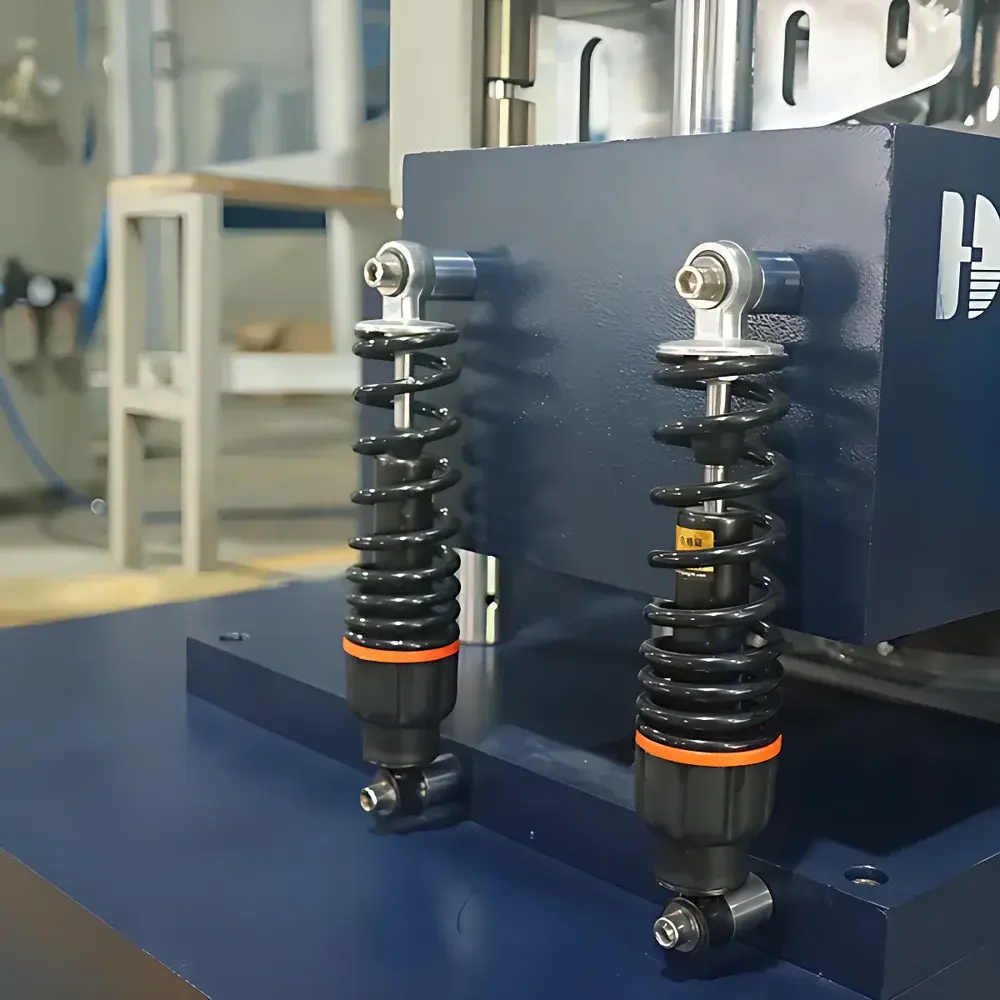
- Dual-stage damping system comprising four hydraulic shock absorbers and heavy-duty pneumatic isolators suppresses transmitted vibration and reduces facility coupling—essential for shared lab environments.
- High-resolution linear displacement encoder mounted at the top crossbeam provides real-time, closed-loop height tracking with ≤0.1 mm resolution, enabling precise correlation between drop height and peak acceleration.
- Pneumatically actuated friction brake with dual-clutch engagement eliminates secondary rebound, preventing unintended double-impact artifacts that compromise test validity per MIL-STD-810F Method 516.7.
- Modular half-sine waveform generator composed of layered elastomeric pads (engineering rubber or wool felt) allows empirical tuning of pulse width (0.5–30 ms) and spectral content via thickness and stiffness configuration—supporting both standard and custom pulse definitions.
- Integrated dual-channel data acquisition supports simultaneous measurement of acceleration (via ICP or charge-mode sensors) and velocity/displacement (via encoder feedback), with 192 kHz sampling ensuring Nyquist compliance for harmonics up to 96 kHz.
Sample Compatibility & Compliance
The HD-G829 accommodates test specimens up to 25 kg mass on its 350 mm × 350 mm anodized aluminum table, with optional fixtures for PCBs, enclosures, battery modules, and avionics line-replaceable units (LRUs). Its mechanical shock profile generation meets full requirements of IEC 60068-2-27 (Ed. 4.0), MIL-STD-810F Method 516.7 (Shock), MIL-STD-202G Method 213 (Mechanical Shock), and GJB 150.18A–2012. All hardware and firmware configurations are documented per ISO/IEC 17025:2017 clause 7.7 (Equipment Records) and support GLP/GMP audit readiness through timestamped calibration logs and user-accessible traceability matrices.
Software & Data Management
Control and analysis are executed via Windows-based HAIDA ShockMaster™ software (v3.2+), compliant with FDA 21 CFR Part 11 for electronic records and signatures. The interface enables parametric definition of drop height, number of drops per orientation, dwell time, and pass/fail thresholds. Real-time oscilloscope-style visualization displays raw acceleration waveforms alongside synthesized metrics (peak g, velocity change Δv, pulse duration, shock response spectrum SRS). All acquired datasets are stored in HDF5 format with embedded metadata (operator ID, timestamp, calibration certificate ID, environmental conditions), supporting automated report generation in PDF or CSV per ISO/IEC 17025 Annex A.2.
Applications
- Qualification of printed circuit board (PCB) solder joint reliability under shipping shock per IPC-9701A.
- Validation of enclosure integrity for ruggedized handheld devices (e.g., military radios, UAV control units) against MIL-STD-810F drop criteria.
- Pre-shipment assessment of lithium-ion battery pack housing deformation and internal cell displacement during simulated logistics impacts.
- Verification of sensor mounting stability in automotive ADAS modules prior to road testing.
- Development of shock-isolation mounts for satellite subsystems undergoing launch environment simulation.
FAQ
What standards does the HD-G829 natively support for shock pulse definition?
It implements half-sine pulse generation aligned with IEC 60068-2-27, MIL-STD-810F Method 516.7, and GJB 150.18A—enabling direct execution of standard test profiles without external waveform synthesis.
Can the system perform multi-axis sequential shock testing?
Yes—by rotating the specimen fixture between drops, users execute orthogonal X/Y/Z axis shock sequences per MIL-STD-883E Method 2002.1; no reconfiguration of the base unit is required.
Is the accelerometer input compatible with industry-standard sensors?
The dual-channel front-end accepts voltage-output (±10 V), IEPE/ICP®, and charge-mode transducers with built-in TEDS support, eliminating need for external signal conditioners.
How is calibration traceability maintained?
Each system ships with NIST-traceable calibration certificates for the displacement encoder and reference accelerometer, updated annually per ISO/IEC 17025 requirements.
Does the software support automated pass/fail evaluation against user-defined limits?
Yes—thresholds can be set for peak acceleration, velocity change, and SRS envelope compliance, with results logged and flagged in real time.


