Inframet DT Series Comprehensive Thermal Imaging Test System
| Brand | Inframet |
|---|---|
| Origin | Poland |
| Model | DT |
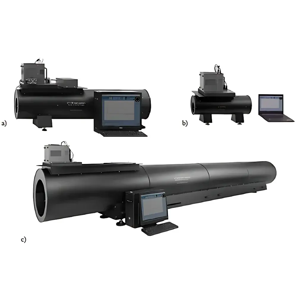
| Configuration Options | DT100 (short-range), DT150 (mid-range), DT400 (long-range) |
| Application Scope | Laboratory & Armory-Based IR Camera Characterization, VIS-NIR Camera Testing, Multi-Sensor Boresighting |
| Compliance Framework | ASTM E1213, ISO 18434-1, MIL-STD-3009 (applicable modules), FDA 21 CFR Part 11–ready software architecture (TAS v5.2+) |
Overview
The Inframet DT Series Comprehensive Thermal Imaging Test System is a modular, projection-based optical test platform engineered for quantitative performance evaluation of thermal imaging systems—including uncooled and cooled infrared cameras (3–5 µm and 8–14 µm spectral bands)—under controlled laboratory or armory conditions. Unlike point-source or blackbody-based testers, the DT system employs a high-stability collimated projection architecture to emulate real-world target scenes at calibrated angular subtense and radiometric contrast. It operates on the principle of spatial frequency domain analysis: standardized test patterns (slits, bar targets, edge targets, noise fields, and uniformity apertures) are projected into the device under test’s (DUT) field of view; the DUT’s digital output is then acquired via synchronized video capture hardware and processed using traceable algorithms to extract objective, ISO/ASTM-compliant metrics. The system supports both manual and fully automated measurement sequences, with all optical paths aligned to a common mechanical reference axis—enabling rigorous co-registration validation between thermal imagers and visible/NIR sensors.
Key Features
- Modular optical configuration: Three base variants—DT100 (optimized for 10 km long-range reconnaissance optics)—each with matched focal length, aperture, and collimation precision.
- Multi-spectral illumination: Integrated LED and halogen sources cover 400–1000 nm (VIS-NIR) and calibrated blackbody-equivalent radiance in IR bands; spectral profiles are NIST-traceable and user-selectable per test standard.
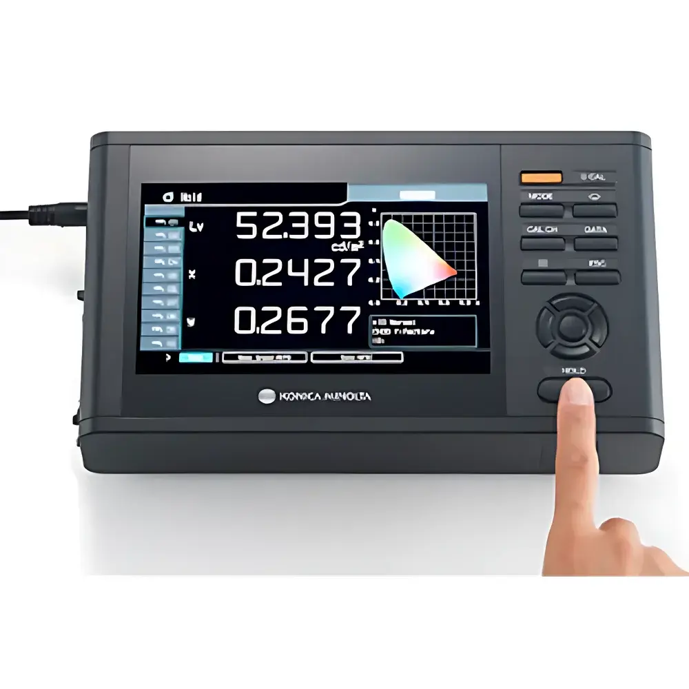
- Dual-path video acquisition: Supports simultaneous analog (PAL/NTSC) and digital (GigE Vision, USB3 Vision) frame grabbers for synchronized thermal + visible channel analysis—critical for boresight error quantification and multi-sensor fusion validation.
- Automated MRTD/MTF/TOD execution: TAS software implements iterative threshold search, edge spread function derivation, and noise power spectrum integration—all compliant with ASTM E1213 (MRTD), ISO 12233 (MTF), and NATO AEP-67 (TOD).
- Full-axis mechanical reference: All optical components—including target wheels, light sources, and collimators—are mounted on a granite optical bench with kinematic mounts and laser-aligned fiducials to ensure ≤2 arcsec repeatability across configurations.
- GLP/GMP-ready data governance: Audit trail logging, electronic signatures, and version-controlled calibration certificates embedded in TAS v5.2+; supports 21 CFR Part 11 compliance when deployed with validated IT infrastructure.
Sample Compatibility & Compliance
The DT system accommodates thermal imagers with FOVs from 0.5° to 20°, F-numbers from f/1.0 to f/4.0, and detector formats up to 1280×1024 pixels (including VOx microbolometers and InSb/MCT FPAs). It also characterizes VIS-NIR cameras (CCD/CMOS) operating in 450–900 nm, with sensitivity down to 0.0001 cd/m² (night mode) and dynamic range exceeding 100 dB. All measurements adhere to internationally recognized standards: MRTD per ASTM E1213-22, NETD per ISO 18434-1:2021, geometric distortion per ISO 9039, and non-uniformity per MIL-STD-3009 Annex B. Optional calibration services include NIST-traceable radiometric verification and spatial frequency standard certification (NPL UK or PTB Germany).
Software & Data Management
TAS (Thermal Analysis Suite) v5.2+ serves as the unified control, acquisition, and reporting engine. It provides scriptable test sequences, real-time parameter visualization (e.g., MTF curves overlaid with theoretical diffraction limits), and export to CSV, HDF5, and XML formats for LIMS integration. Raw image data is stored with embedded metadata (exposure time, source radiance, ambient temperature, lens ID, operator ID). The software includes built-in uncertainty propagation models per GUM (JCGM 100:2018) for all derived parameters—including auto-MRTD confidence intervals and SiTF variance estimation. Validation documentation (IQ/OQ/PQ protocols) and 21 CFR Part 11 configuration files are supplied with each system.
Applications
- End-of-line verification of military-grade thermal sights (e.g., AN/PAS-13, Thales Catherine series) against MIL-STD-3009 requirements.
- Development-stage optimization of cooled MWIR camera optics—quantifying focus shift vs. temperature, stray light rejection, and cold shield efficiency.
- Boresight alignment validation for dual-band gimbals (e.g., FLIR Star SAFIRE, Leonardo Osprey), including planar and axial misalignment decomposition.
- ISO 18434-1-compliant condition monitoring of industrial thermography systems used in predictive maintenance programs.
- Academic research on IR sensor phenomenology—e.g., 3D noise modeling, temporal non-uniformity drift under thermal cycling, and photon shot noise contribution to NETD.
FAQ
What is the minimum measurable NETD for a cooled MWIR camera using the DT400 configuration?
NETD measurement uncertainty is dependent on DUT integration time and scene temperature stability; typical repeatability is ±0.03 K (k = 2) for cameras with integration times ≥10 ms and ambient drift <0.1 K/h.
Can the DT system validate automatic gain control (AGC) behavior across dynamic scenes?
Yes—via programmable temporal sequences using the MOSOT motion simulator and variable-radiance LED array, enabling step-response, ramp-response, and histogram-based AGC characterization.
Is third-party calibration of the projection system required annually?
Inframet recommends biennial NIST-traceable radiometric recalibration and annual geometric verification using certified reticles; full system IQ/OQ can be performed on-site by certified field engineers.
Does TAS support custom algorithm integration via API?
TAS exposes a COM/.NET API and Python bindings (via pyTAS) for embedding proprietary MTF deconvolution or neural noise reduction models into the measurement pipeline.
How is boresight error decomposed into pitch/yaw/roll components?
Using the Movis dual-camera module: one imager captures the thermal DUT’s reticle projection while the other records the visible reference axis; vector algebra computes all six degrees of freedom with sub-pixel resolution.