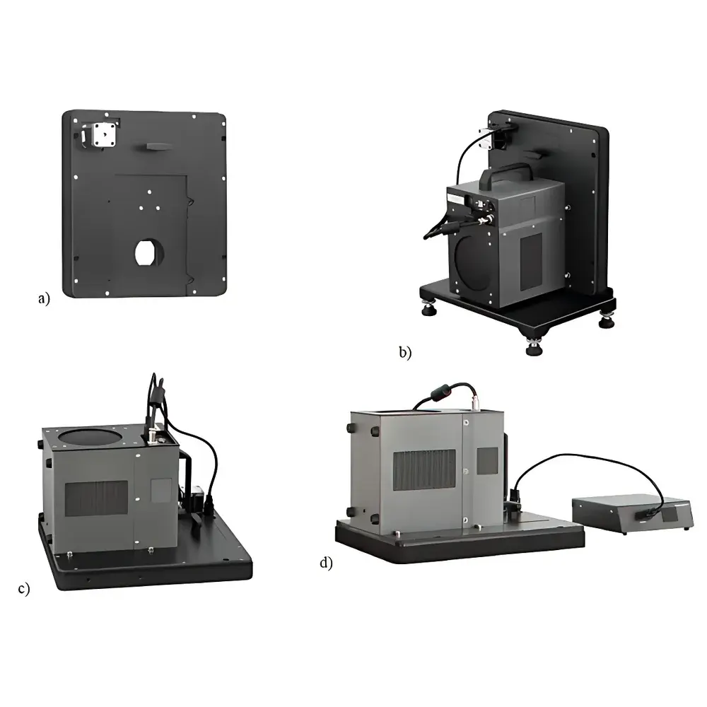
Inframet MRW-8 Motorized Rotating Target Wheel
| Brand | Inframet |
|---|---|
| Origin | Poland |
| Model | MRW-8 |
| Target Wheel Aperture Count | 8 |
| Positioning Uncertainty (Standard) | < 0.15 mm |
| Positioning Uncertainty (Custom High-Precision Version) | 0.05 mm |
| Emissivity of Coated Surface | ≥ 0.97 |
| Interface Compatibility | CDT Collimator, TCB Blackbody, DCB Multispectral Blackbody, DAL/SAL Radiation Sources |
| Control Options | PC-based software via external controller (BBB/B variants), manual electronic control (C variant) |
| Aperture Geometry Options | Circular (standard), square (7+1 configuration in A variant) |
Overview
The Inframet MRW-8 Motorized Rotating Target Wheel is a precision electro-mechanical subsystem designed for integration into radiometric and electro-optical (EO) test benches—specifically those employing collimated optical paths for the characterization of infrared imaging systems, thermal cameras, and multispectral sensors. It operates within the focal plane of a CDT-series collimator, enabling automated, repeatable substitution of calibrated target patterns without mechanical realignment of the optical train. The MRW-8 functions on the principle of controlled angular indexing: an 8-position rotary stage precisely positions each target aperture into the collimated beam path, ensuring consistent illumination geometry and minimizing vignetting-induced measurement drift. Its high-emissivity black coating (ε ≥ 0.97 across 3–14 µm) guarantees uniform thermal signature presentation when used with blackbody radiation sources such as the TCB (Temperature-Controlled Blackbody) or DCB (Dual-Cavity Blackbody), while its rigid aluminum construction and kinematic mounting interface ensure long-term dimensional stability under laboratory thermal cycling.
Key Features
- Motorized 8-position indexing wheel with programmable dwell time and bidirectional rotation capability
- Standard positioning uncertainty < 0.15 mm at the focal plane; optional high-precision variant achieves ≤ 0.05 mm uncertainty through enhanced bearing preload and encoder resolution
- Black anodized surface coated with spectrally stable, high-emissivity paint (ε ≥ 0.97 from 3 to 14 µm), qualified per ASTM E1933 and ISO 18434-1 for radiometric calibration traceability
- Modular mechanical interface compatible with Inframet’s CDT collimators and standardized flange mounts for TCB/DCB blackbodies and DAL/SAL broadband sources
- Three configurable control architectures: (A) PC-software-driven via TCB internal controller; (B) external motion controller synchronized with PC acquisition software; (C) manual electronic jog control using front-panel buttons and status LED indicators
- Aperture layout flexibility: standard circular apertures (8×); optional 7+1 square-aperture configuration for dual-mode testing (e.g., spatial resolution + MTF verification)
Sample Compatibility & Compliance
The MRW-8 is engineered to support standardized EO test protocols defined in MIL-STD-3009, IEEE 1858 (CPIQ), and ISO 12233 Annex D for spatial frequency response validation. It accommodates target patterns conforming to USAF 1951, Siemens star, slanted-edge, and differential line-pair configurations—mounted on removable, metrologically certified substrate plates. All mechanical interfaces comply with ISO 10110-1 for optical component mounting tolerances. When integrated into a full EO test station, the system supports GLP-compliant audit trails when paired with Inframet’s ICS-2000 software suite, which logs timestamped position commands, thermal source setpoints, and image acquisition triggers in accordance with FDA 21 CFR Part 11 requirements for electronic records and signatures.
Software & Data Management
The MRW-8 does not include embedded firmware but relies on host-level command interpretation via RS-232, USB CDC, or Ethernet (TCP/IP) interfaces. Inframet provides native drivers and API libraries for LabVIEW, MATLAB, and Python (PySerial/PyVISA), enabling synchronized sequencing with frame-grabbers, blackbody controllers, and radiometric data loggers. Position confirmation is returned via quadrature encoder feedback or Hall-effect sensor pulses, supporting closed-loop verification. Configuration files (.mrwxml) store aperture metadata—including physical dimensions, center coordinates, and associated NIST-traceable calibration certificates—ensuring reproducibility across laboratories and inter-laboratory comparison studies.
Applications
- Radiometric calibration of cooled and uncooled IR imagers using variable-temperature blackbody references
- Spatial resolution assessment (MTF, LSF, ESF) via slanted-edge and knife-edge targets under collimated conditions
- Non-uniformity correction (NUC) pattern generation for microbolometer and QWIP focal plane arrays
- Dynamic range and saturation threshold testing using stepped gray-scale or multi-temperature target sequences
- Multi-spectral sensor alignment verification when paired with DAL/SAL tunable sources and spectral filters
- Automated production-line verification of EO modules per ISO/IEC 17025-accredited test procedures
FAQ
What is the maximum operating temperature ambient for continuous MRW-8 operation?
The MRW-8 is rated for continuous use in environments between 15 °C and 30 °C, with relative humidity ≤ 60 % non-condensing. Extended exposure above 35 °C may affect encoder repeatability and coating longevity.
Can the MRW-8 be retrofitted with custom apertures or non-standard coatings?
Yes—Inframet offers OEM customization including substrate material changes (e.g., Invar for ultra-low thermal expansion), alternative spectral coatings (e.g., gold for visible-NIR reflectance standards), and bespoke aperture geometries under NDA and metrological validation agreements.
Is firmware upgrade support available for legacy MRW-8 units?
Firmware updates are provided exclusively for units purchased with Inframet’s extended service contract (ESC); no field-upgradable microcode is embedded—control logic resides entirely in host software.
Does the MRW-8 meet electromagnetic compatibility (EMC) requirements for Class I laboratory equipment?
Yes—the device complies with EN 61326-1:2013 for electromagnetic immunity and emission limits applicable to professional laboratory instrumentation.
How is positional accuracy verified during factory calibration?
Each unit undergoes interferometric verification using a Zygo Verifire™ XP laser interferometer; raw displacement data and uncertainty budgets are included in the Certificate of Conformance shipped with the instrument.