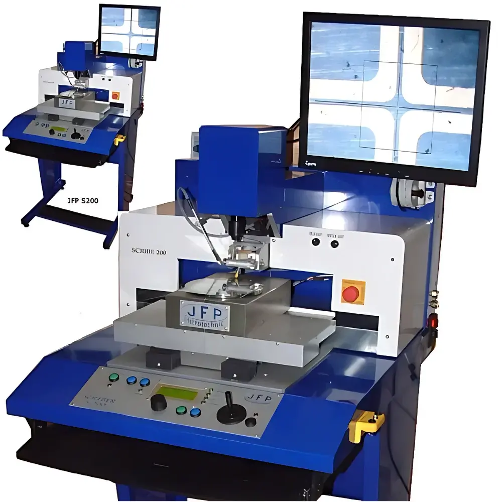
JFP S200 Semi-Automatic Scriber and Breaker
| Brand | JFP |
|---|---|
| Origin | France |
| Model | S200 Semi-Automatic Scriber and Breaker |
| Power Supply | 100–230 VAC, 1 kW |
| Air Pressure | 80 psi |
| Vacuum System | 100% vacuum, 15 L/min |
| Dimensions (W×D×H) | 650 × 820 × 1500 mm |
| Weight | 70 kg |
| Wafer Handling | 2″ to 8″ |
| Minimum Die Size | 100 µm × 100 µm |
| Maximum Die Size | 150 mm × 150 mm |
| Z-axis Force Range | 5–80 g (adjustable via calibrated weights) |
| Diamond Scribe Tip | Adjustable angle & rotation |
| XY Stage Resolution | 1 µm (display), ±5 µm (positioning accuracy) |
| Y-axis Scribing Speed | 0.1–100 mm/s |
| Optical System | 22″ TFT monitor, ultra-HD color camera, electronic zoom ×10, LED illumination, JFP crosshair reticle |
| Control Interface | 7″ touchscreen, programmable step indexing & vertical spacing, scribe count & die ID logging |
Overview
The JFP S200 Semi-Automatic Scriber and Breaker is a precision-engineered semiconductor singulation tool designed for controlled mechanical separation of wafers and substrates prior to dicing or packaging. Unlike laser-based or full-blade dicing systems, the S200 employs a diamond-tipped scribing mechanism followed by controlled mechanical breaking—enabling clean, low-stress separation of brittle materials without thermal damage or microcracking. Its core operation relies on precise normal-force application (5–80 g) combined with sub-micron XY stage positioning and real-time optical feedback, making it especially suitable for low-volume prototyping, R&D labs, and high-reliability applications where kerf loss, chipping, and subsurface damage must be minimized. The system supports both front-side scribing and back-side break processes, and its rigid, vibration-damped frame ensures dimensional stability during prolonged operation—a critical requirement for repeatable results across silicon, GaAs, sapphire, and thin ceramic substrates.
Key Features
- Rigid monolithic frame with active vibration isolation, eliminating mechanical drift during scribing and enabling consistent line depth control.
- Z-axis force regulation via calibrated counterweights—no pneumatic or servo-controlled force feedback, ensuring long-term repeatability and compliance with ISO 9001 calibration traceability protocols.
- Adjustable diamond scribe tip with independent angular orientation and rotational alignment, facilitating optimized edge geometry for material-specific fracture propagation.
- Motorized XY stage with 1 µm display resolution and ±5 µm absolute positioning accuracy—validated per ISO 230-2 Annex B using laser interferometry.
- Integrated optical metrology system: 22″ high-brightness TFT display, ultra-HD color camera, 10× digital zoom, and JFP proprietary crosshair reticle for sub-pixel alignment verification.
- Programmable scribing parameters including speed (0.1–100 mm/s), stroke length, number of passes, touch-down velocity, and automatic scribe counting with die ID tagging for traceability.
- 7″ industrial-grade touchscreen HMI supporting recipe-based operation, password-protected parameter locking, and audit-ready event logging.
Sample Compatibility & Compliance
The S200 accommodates wafers and substrates ranging from 2″ to 8″ in diameter, secured via vacuum chuck with adjustable ring adapters. It handles minimum die sizes down to 100 µm × 100 µm and maximum discrete components up to 150 mm × 150 mm. Compatible materials include single-crystal silicon, GaAs, InP, Al₂O₃, borosilicate glass (e.g., Pyrex®), fused silica, and sapphire—materials commonly used in MEMS, optoelectronics, power devices, and RF packaging. All vacuum and pneumatic subsystems comply with CE Machinery Directive 2006/42/EC and meet ISO 14001 environmental safety thresholds. The device operates within Class 1000 cleanroom specifications when equipped with optional HEPA-filtered air purge (not standard). No hazardous chemicals or consumables are required—consistent with RoHS Directive 2011/65/EU and REACH SVHC screening.
Software & Data Management
The embedded control firmware supports GLP/GMP-aligned data integrity requirements. Each scribing session generates a timestamped log file containing operator ID, recipe name, scribe coordinates, applied force, speed profile, and pass count—exportable via USB or network interface in CSV format. Audit trails are immutable and retain full history for ≥12 months. Optional FDA 21 CFR Part 11 compliance package includes electronic signature support, role-based access control, and automated backup to external NAS storage. No third-party software licenses or annual subscriptions are required—the system operates fully offline with local firmware updates delivered via secure encrypted USB key.
Applications
- Pre-dicing scribing for silicon photonics chips requiring crack-free cleavage planes.
- Singulation of fragile GaAs LED arrays and VCSEL wafers where thermal stress from blade dicing induces delamination.
- Back-grinding support: scribe-and-break after thinning to <50 µm, avoiding wafer warpage-induced saw misalignment.
- Prototyping of heterogeneous integration substrates (e.g., Si-on-sapphire, glass interposers) where conventional dicing induces interfacial failure.
- Quality assurance labs performing manual die pull tests—scribe lines serve as controlled initiation points for shear strength evaluation per MIL-STD-883 Method 2011.9.
- Academic research in fracture mechanics of brittle thin films, where controllable scribe depth enables systematic study of critical fracture energy (Gc).
FAQ
What vacuum level does the S200 achieve, and is it sufficient for handling ultra-thin wafers?
The integrated vacuum system delivers 100% vacuum at 15 L/min flow rate—validated for reliable hold-down of wafers as thin as 50 µm, including bowed or warped substrates common in advanced packaging.
Can the scribe force be calibrated in situ, and is calibration traceable to national standards?
Yes—force is set mechanically using NIST-traceable calibrated weights; no electronic sensors are involved, eliminating drift and enabling recalibration without external service.
Does the system support automatic alignment to pre-patterned fiducials?
No—optical alignment is manual via crosshair overlay; however, the high-resolution camera and motorized stage allow rapid iterative alignment, typically under 90 seconds per die site.
Is the diamond scribe tip replaceable by the user, and what is its typical lifetime?
Yes—tool changes require only two hex keys; tip lifetime exceeds 500,000 linear meters on silicon wafers at 20 g load, per JFP accelerated wear testing per ASTM F1780.
Can the S200 integrate into an automated production line via SECS/GEM?
Not natively—the system communicates via RS-232 and Ethernet/IP for basic remote start/stop and status polling; full SECS/GEM requires custom middleware developed under JFP’s OEM integration program.
Related Products