JFQ-1150 E Online Biogas Analyzer by Junfang Physical & Chemical
| Brand | Junfang Physical & Chemical |
|---|---|
| Origin | Beijing, China |
| Model | JFQ-1150 E |
| CH₄ | 0–100% vol |
| CO₂ | 0–50% vol |
| CO | 0–20% vol |
| H₂S | 0–1.00% vol |
| O₂ | 0–25% vol |
| H₂ | 0–10% vol (optional) |
| Accuracy | ≤ ±1% FS |
| Repeatability | ≤ ±1% FS |
| Linearity | ≤ ±1% FS |
| Alarm Range | 10–90% FS (user-configurable) |
| Output | 4–20 mA analog + RS-232 digital |
| Display | Full-color TFT touchscreen |
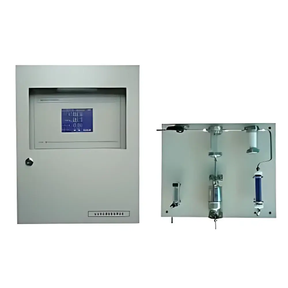
| Preconditioning | Integrated stainless-steel gas conditioning system with pressure stabilization, primary & secondary water removal (coalescing + silica gel), particulate filtration, and automatic liquid drainage |
Overview
The JFQ-1150 E Online Biogas Analyzer is an industrial-grade, continuous-emission monitoring (CEM) instrument engineered for real-time, multi-component analysis of raw and conditioned biogas streams in anaerobic digestion facilities, landfill gas recovery plants, and wastewater treatment biogas upgrading systems. It employs a hybrid sensor architecture grounded in fundamental physical measurement principles: non-dispersive infrared (NDIR) spectroscopy for CH₄, CO₂, CO, and H₂S; thermal conductivity detection (TCD) for H₂; and long-life electrochemical sensing for O₂. This multi-principle approach ensures analytical independence across species—eliminating cross-sensitivity artifacts common in single-technology platforms—and delivers stable, traceable measurements under variable gas matrix conditions. Designed for unattended operation in harsh ambient environments (IP65-rated enclosure, -10 to 50 °C operating range), the analyzer meets the functional requirements of ISO 16000-31 (indoor air—biogas composition), ASTM D1945 (gas analysis by GC), and supports compliance pathways for EU Directive 2009/28/EC (renewable energy) and US EPA Method 2C (gaseous emissions).
Key Features
- Integrated stainless-steel gas preconditioning system featuring dual-stage moisture removal: coalescing separator for bulk liquid water extraction followed by desiccant (silica gel) bed for residual vapor control—ensuring dew point < 5 °C at analyzer inlet
- Pressure-regulated sampling path (±0.5 kPa stability) with automated condensate expulsion via gravity-fed drain trap, eliminating manual maintenance intervals
- True multi-gas capability: simultaneous quantification of up to six components (CH₄, CO₂, CO, H₂S, O₂, H₂) with independent calibration protocols per sensor technology
- High-integrity signal architecture: galvanically isolated 4–20 mA outputs (HART-compatible) plus RS-232 serial interface supporting Modbus RTU protocol for SCADA integration
- Embedded touchscreen HMI with intuitive wizard-driven calibration, alarm configuration, and diagnostic logging—no external PC required for routine operation
- Modular sensor design enabling field-replaceable transducers without system shutdown; all critical components rated for ≥24 months continuous service life under typical biogas conditions
Sample Compatibility & Compliance
The JFQ-1150 E accepts raw biogas (typical composition: 50–75% CH₄, 25–45% CO₂, 0–1% H₂S, 0–1% O₂, trace CO/H₂) with inlet pressure up to 150 kPa(g) and particulate loading < 5 mg/m³. Its preconditioning train complies with EN 15267-3 (performance certification of CEM systems) requirements for sample conditioning robustness. All gas-contact surfaces are electropolished 316L stainless steel; no elastomers or polymer seals exposed to process stream. The analyzer satisfies GLP-aligned data integrity criteria: full audit trail of calibration events, user logins, parameter changes, and alarm triggers—exportable as CSV with timestamped metadata. Optional firmware upgrade enables 21 CFR Part 11-compliant electronic signatures and role-based access control.
Software & Data Management
Onboard firmware includes embedded data logger (10,000-point circular buffer, 1-second resolution) with automatic timestamping synchronized to NTP server via optional Ethernet module. Raw sensor outputs, compensated concentration values, and system health metrics (e.g., filter differential pressure, desiccant saturation indicator) are stored locally and accessible via web interface (HTTP/HTTPS) or serial query. Export formats include CSV and XML compliant with ISA-95 Level 2 MES integration standards. Calibration history—including span gas certificates, zero drift logs, and response time validation—is retained for ≥5 years. Remote diagnostics support secure SSH tunneling for OEM-level troubleshooting without exposing internal network infrastructure.
Applications
- Real-time optimization of anaerobic digester feedstock ratio and retention time via CH₄/CO₂ ratio trending
- Early detection of process upsets (e.g., acidosis, sulfate reduction) through H₂S/O₂ anomaly correlation
- Feedforward control of biogas upgrading units (amine scrubbing, PSA, membrane separation) using CH₄ purity feedback
- Landfill gas flare efficiency monitoring per EPA 40 CFR Part 60 Subpart WWW requirements
- Carbon credit verification under Verra VM0037 (Renewable Biomethane) methodology via certified CH₄ mass flow calculation
- Pre-combustion safety interlock signaling based on O₂ and H₂ thresholds in combined heat and power (CHP) skids
FAQ
What gas conditioning is required upstream of the JFQ-1150 E?
None—the integrated stainless-steel preconditioning system handles pressure stabilization, bulk water removal, particulate filtration, and deep drying. Only a clean, dry sample line (1/4″ SS tubing) from the process tap is needed.
Can the analyzer operate continuously during digester start-up when H₂S levels exceed 1,000 ppm?
Yes. The NDIR H₂S channel uses optical filtering and temperature-compensated detectors validated to 5,000 ppm, with auto-ranging to maintain accuracy across full 0–1.00% scale.
Is third-party calibration certification available?
Yes. Factory calibration certificates traceable to NIST-standard gas mixtures (certified per ISO/IEC 17025) are provided with each unit. On-site verification services include span gas challenge testing per ISO 6145-7.
How is sensor drift managed over extended deployment?
Automated zero calibration cycles initiate daily using internal reference gas (N₂ balance); span calibration is user-scheduled or triggered by alarm thresholds. Drift compensation algorithms apply real-time correction based on thermal and pressure sensor feedback.
Does the system support redundant communication paths?
Standard configuration includes RS-232 and isolated 4–20 mA. Optional modules add RS-485 (Modbus RTU), Ethernet (TCP/IP), or 4G LTE telemetry for off-grid sites.


")
