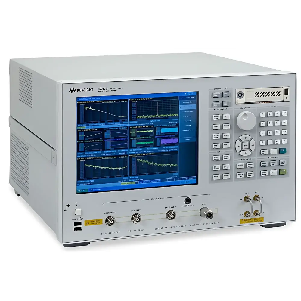
Keysight Technologies Customized-11 Signal Source Analyzer
| Brand | Keysight Technologies |
|---|---|
| Origin | USA |
| Model | customized-11 |
| Frequency Range (RF Input) | 10 MHz to 110 GHz |
| Offset Frequency Range | 1 Hz to 100 MHz |
| Transient Capture Bandwidth | up to 80 MHz (narrowband), up to 4.8 GHz (wideband) |
| Phase & AM Noise Measurement Capability | Yes |
| Baseband Noise Analysis | 1 Hz – 100 MHz |
| Real-time Spectrum Monitoring Span | up to 15 MHz |
| Time-Domain Transient Resolution | femtosecond-level jitter analysis |
| DC Source Integration | Low-noise frequency/power/DC bias (Vc/Vs/I) for VCO characterization |
Overview
The Keysight Technologies Customized-11 Signal Source Analyzer is a high-performance, modular instrumentation platform engineered for precision characterization of signal integrity, spectral purity, and dynamic behavior in RF, microwave, and millimeter-wave sources. Operating on the principle of cross-correlation-based phase noise measurement and real-time heterodyne downconversion, it delivers traceable, low-uncertainty analysis of oscillator stability, synthesizer spurious content, and clock jitter—critical parameters in 5G NR, satellite communications, radar systems, and high-speed serial link development. Its architecture supports both continuous-wave (CW) and modulated source evaluation, with calibrated measurements traceable to NIST standards and compliant with IEEE Std 1139 and ITU-R SM.328 recommendations for phase noise metrology.
Key Features
- Wide RF input coverage from 10 MHz to 110 GHz, enabling direct analysis of fundamental and harmonic outputs without external mixers or preselectors.
- Ultra-low-noise internal reference path and dual-channel cross-correlation engine ensure phase noise floor as low as –190 dBc/Hz at 1 MHz offset (typical, 10 GHz carrier), meeting stringent requirements for ultra-stable oscillator validation.
- Simultaneous time-synchronized acquisition of frequency, phase, and power transients—capturing microsecond-scale frequency hops, thermal drift, and settling behavior with femtosecond timing resolution via integrated time-interval analyzer functionality.
- Dedicated video trigger architecture allows deterministic capture of rare or non-repetitive events such as voltage-controlled oscillator (VCO) mode switching, PLL unlock sequences, or supply-induced frequency jumps.
- Integrated low-noise DC bias sources (±15 V, ±100 mA) with programmable slew rate control enable full VCO/VCXO characterization—including tuning sensitivity (MHz/V), push-pull coefficients, and supply modulation response—within a single instrument environment.
- Real-time spectrum monitoring up to 15 MHz span with 100% probability of intercept (POI) at ≥100 µs dwell time supports dynamic spectral occupancy analysis during transient operation.
Sample Compatibility & Compliance
The Customized-11 accommodates a broad range of signal sources including crystal oscillators (XO, TCXO, OCXO), voltage-controlled oscillators (VCOs), phase-locked loops (PLLs), frequency synthesizers, and mmWave signal generators. It supports standard RF connectors (2.92 mm, 1.0 mm) and optional waveguide interfaces for WR-10 and WR-8 bands. All measurements adhere to ISO/IEC 17025-accredited calibration practices when used with Keysight’s certified calibration services. The system complies with electromagnetic compatibility (EMC) per CISPR 16-2-3 and safety requirements under IEC 61010-1. For regulated environments, optional firmware enables audit-trail logging and user access controls aligned with FDA 21 CFR Part 11 and EU Annex 11 requirements.
Software & Data Management
Controlled via Keysight PathWave Vector Signal Analysis (VSA) software or custom Python/LabVIEW APIs, the analyzer supports automated test sequencing, statistical process monitoring (SPC), and export of measurement data in HDF5, CSV, and MATLAB .mat formats. Raw IQ data, phase noise traces, jitter histograms, and transient waveforms are timestamped and stored with full metadata—including instrument configuration, environmental sensor readings (optional), and calibration certificate IDs. Integrated data management tools support version-controlled report generation compliant with MIL-STD-45662A and ISO 9001 documentation protocols.
Applications
- Phase noise and AM noise characterization of local oscillators in phased-array radar front-ends.
- Femtosecond-level clock jitter decomposition (TIE, DCD, SJ, RJ) for SerDes compliance testing per IEEE 802.3bj and OIF CEI-28G.
- Dynamic VCO linearity and tuning hysteresis mapping under temperature-varying bias conditions.
- Verification of frequency agility and settling time in agile synthesizers for cognitive radio and electronic warfare systems.
- Baseband noise profiling of power supply rejection ratio (PSRR) in RFIC bias networks.
- Time-domain analysis of frequency modulation distortion in wideband DAC-driven signal sources.
FAQ
What is the minimum measurable offset frequency for phase noise analysis?
The analyzer supports offset frequencies starting from 1 Hz, enabling flicker noise (1/f) region characterization essential for ultra-low-noise oscillator design.
Can the system perform simultaneous phase noise and power transient measurements?
Yes—hardware-synchronized dual-channel acquisition captures phase, frequency, and power deviations with sub-nanosecond timestamp alignment.
Is external calibration required before use?
Factory calibration is performed per ANSI/NCSL Z540-1; periodic recalibration is recommended every 12 months or after 200 hours of operation in critical applications.
Does the analyzer support third-party DUT control integration?
Full SCPI command set and IVI-COM drivers enable seamless integration with PXIe chassis, temperature chambers, and programmable power supplies.
How is traceability maintained for regulatory submissions?
Each measurement includes embedded calibration chain identifiers, uncertainty budgets calculated per GUM (JCGM 100:2008), and digital signatures compatible with electronic record retention systems.