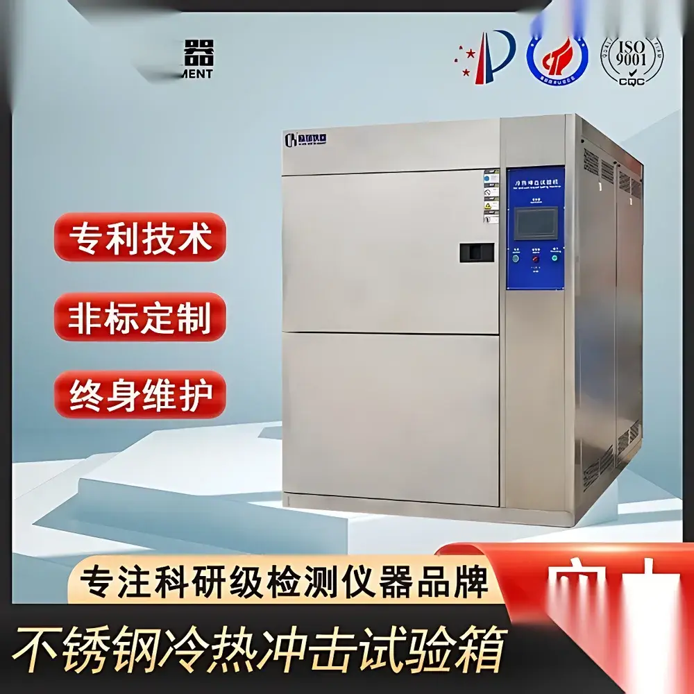
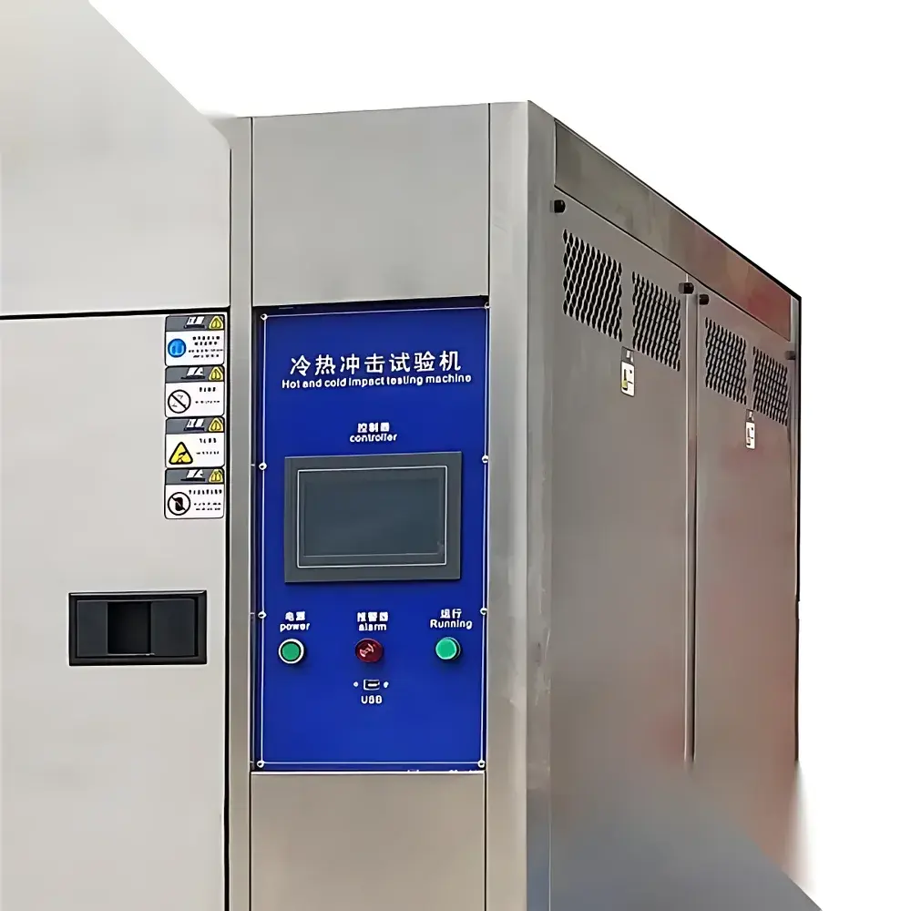
LED High-Temperature Thermal Shock Test Chamber
| Brand | OEM |
|---|---|
| Origin | Imported |
| Manufacturer Type | Authorized Distributor |
| Price | USD 12,500 (FOB Shanghai) |
| Internal Dimensions (W×H×D) | 40×35×30 cm to 70×60×60 cm |
| Temperature Range | Hot Zone: RT to +200 °C |
| Cold Zone | RT to −70 °C |
| Test Zone | +60 °C to +150 °C (Hot Shock), 0 °C to −65 °C (Cold Shock) |
| Switching Mechanism | Pneumatic Air-Door Isolation (Static Specimen) |
| Recovery Time | <5 min |
| Temp. Uniformity | ±2.0 °C |
| Temp. Stability | ±0.5 °C |
| Refrigeration | Dual-Stage Cascade System (R404A/R23), Water-Cooled, German Semi-Hermetic Compressors |
| Construction | Interior – Mirror-Finish SUS304 Stainless Steel |
| Insulation | High-Density Fire-Retardant PU Foam |
| Compliance | GB/T 2423.1–2001, GB/T 2423.2–2001, GB/T 2423.22–2002, GJB 150.3–1986 / 150.4–1986 / 150.5–1986, IEC 60068-2-14 (Test N), MIL-STD-810G Method 503.5, EIA-364-32, QC/T 17–1992 |
Overview
The LED High-Temperature Thermal Shock Test Chamber is an engineered environmental test system designed for accelerated evaluation of material and component reliability under rapid, repetitive thermal transitions. It operates on the principle of controlled, high-rate temperature cycling between independently maintained hot and cold reservoirs—enabling precise simulation of real-world thermal stress events such as solder joint fatigue, interfacial delamination, seal integrity failure, and coefficient-of-thermal-expansion (CTE) mismatch in electronic assemblies, automotive modules, aerospace composites, and polymer-based enclosures. Unlike steady-state temperature chambers, this system implements a static specimen configuration: the test article remains stationary within the central test compartment while thermally isolated air doors pneumatically route conditioned airflow from either the heated or cooled reservoir. This architecture eliminates mechanical motion artifacts (e.g., vibration, positional drift), ensuring measurement repeatability and minimizing extraneous stress variables during qualification per MIL-STD-810G or IEC 60068-2-14.
Key Features
- Dual-reservoir cascade refrigeration architecture with German semi-hermetic compressors, enabling stable operation at −70 °C in the cold zone and +200 °C in the hot zone
- Pneumatically actuated stainless steel air doors with low-leakage sealing, ensuring <5-minute thermal recovery time between shock phases
- Mirror-finish SUS304 stainless steel interior chamber walls and insulation using fire-retardant, high-density polyurethane foam (λ ≤ 0.022 W/m·K)
- Independent PID-controlled temperature regulation for hot/cold reservoirs and test zone, with ±0.5 °C stability and ±2.0 °C uniformity across the working volume
- Configurable internal dimensions (40×35×30 cm to 70×60×60 cm) supporting custom fixture integration and multi-unit parallel testing
- Standard 50-mm diameter cable port (SUS304), dual-tier adjustable stainless steel shelves, and rear-mounted 3-phase 380 V AC power inlet (2.5 m cable)
- Environmentally compliant refrigerant blend (R404A/R23) meeting current EU F-Gas Regulation Annex I thresholds
Sample Compatibility & Compliance
The chamber accommodates rigid and semi-rigid specimens up to 60 kg (depending on model), including printed circuit board assemblies (PCBAs), molded connectors, battery modules, optical sensor housings, and structural composite coupons. Its static test configuration preserves sample orientation and eliminates inertial loading—critical for evaluating microcrack propagation in brittle ceramics or adhesive bondline integrity in hybrid packaging. The system fully satisfies thermal shock test requirements defined in GB/T 2423.22–2002 (Temperature Change), GJB 150.5–1986 (Military Standard Temperature Shock), IEC 60068-2-14 (Test N), and EIA-364-32 (Thermal Shock for Electrical Connectors). It supports GLP-compliant validation protocols through traceable calibration records and configurable alarm logging (e.g., door open duration, temperature deviation >±1.0 °C for >30 s).
Software & Data Management
Equipped with an embedded industrial controller featuring 7-inch TFT-LCD HMI, the chamber provides real-time monitoring of all critical parameters: reservoir temperatures, test zone setpoint/actual, door position status, compressor discharge pressure, and coolant flow rate. Data is logged at user-selectable intervals (1–60 s) and exportable via USB 2.0 to CSV format. Optional Ethernet interface enables remote supervision via Modbus TCP or OPC UA, allowing integration into centralized lab management systems (LIMS) and audit-ready data archiving. All operational events—including manual overrides, calibration adjustments, and alarm triggers—are timestamped and stored with user ID attribution, satisfying FDA 21 CFR Part 11 requirements for electronic records when paired with role-based access control firmware.
Applications
- Qualification testing of automotive ECUs per QC/T 17–1992 and ISO 16750-4
- Reliability screening of lead-free solder joints in consumer electronics per J-STD-020
- Validation of hermetic seal performance in MEMS sensors and medical device housings
- Accelerated aging of polymer encapsulants and conformal coatings under thermal cycling stress
- Pre-certification testing for aerospace avionics per MIL-STD-810G Method 503.5
- Material science research on phase transition kinetics in shape-memory alloys and thermoplastic elastomers
FAQ
What distinguishes a static-chamber thermal shock system from a basket-type (two-box) design?
Static-chamber systems maintain specimen position throughout testing—eliminating mechanical shock from basket movement—thereby isolating thermal stress effects alone. Basket-type systems introduce acceleration forces that may confound failure mode analysis.
Is external cooling water infrastructure mandatory?
Yes. The dual-stage cascade refrigeration requires a dedicated closed-loop cooling water supply delivering ≥10 m³/h at ≤32 °C inlet temperature. A field-installed cooling tower is required; chiller integration is not supported.
Can the chamber be validated for ISO/IEC 17025-compliant calibration?
Yes. The system supports third-party sensor mapping per ISO/IEC 17025 Annex B, with NIST-traceable PT100 probes installed at nine spatial locations per IEC 60068-3-5.
What safety interlocks are implemented?
Dual redundant door-position switches, overtemperature cutouts (hot/cold zones), high-pressure shutdown on both refrigeration circuits, and emergency power-off (EPO) with mechanical latch.
Does the controller support automated test sequencing per GJB 150.5?
Yes. Predefined profiles include dwell time, ramp rate, cycle count, and pass/fail criteria per GJB 150.5–1986, with automatic report generation upon completion.


