LED Thermal Shock Test Chamber
| Brand | OEM |
|---|---|
| Origin | Imported |
| Manufacturer Type | Authorized Distributor |
| Price | USD 12,500 (FOB) |
| Internal Dimensions (W×H×D) | 40×35×30 cm to 70×60×60 cm |
| Temperature Range | High Zone: RT to +200 °C |
| Low Zone | RT to −70 °C |
| Test Zone | +60 °C to +150 °C (hot shock) |
| Switching Method | Pneumatic damper–actuated air valve |
| Recovery Time | <5 min |
| Temp. Uniformity | ±2.0 °C |
| Temp. Control Accuracy | ±0.5 °C |
| Refrigeration | Dual-stage cascade system with semi-hermetic compressors (R404A/R23) |
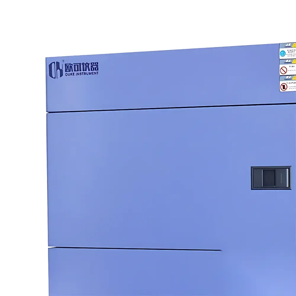
| Construction | Interior—SUS304 mirror-finish stainless steel |
| Insulation | High-density fire-retardant PU foam |
| Power Supply | AC 380 V ±5%, 50 Hz ±0.5 Hz, 3-phase 5-wire |
Overview
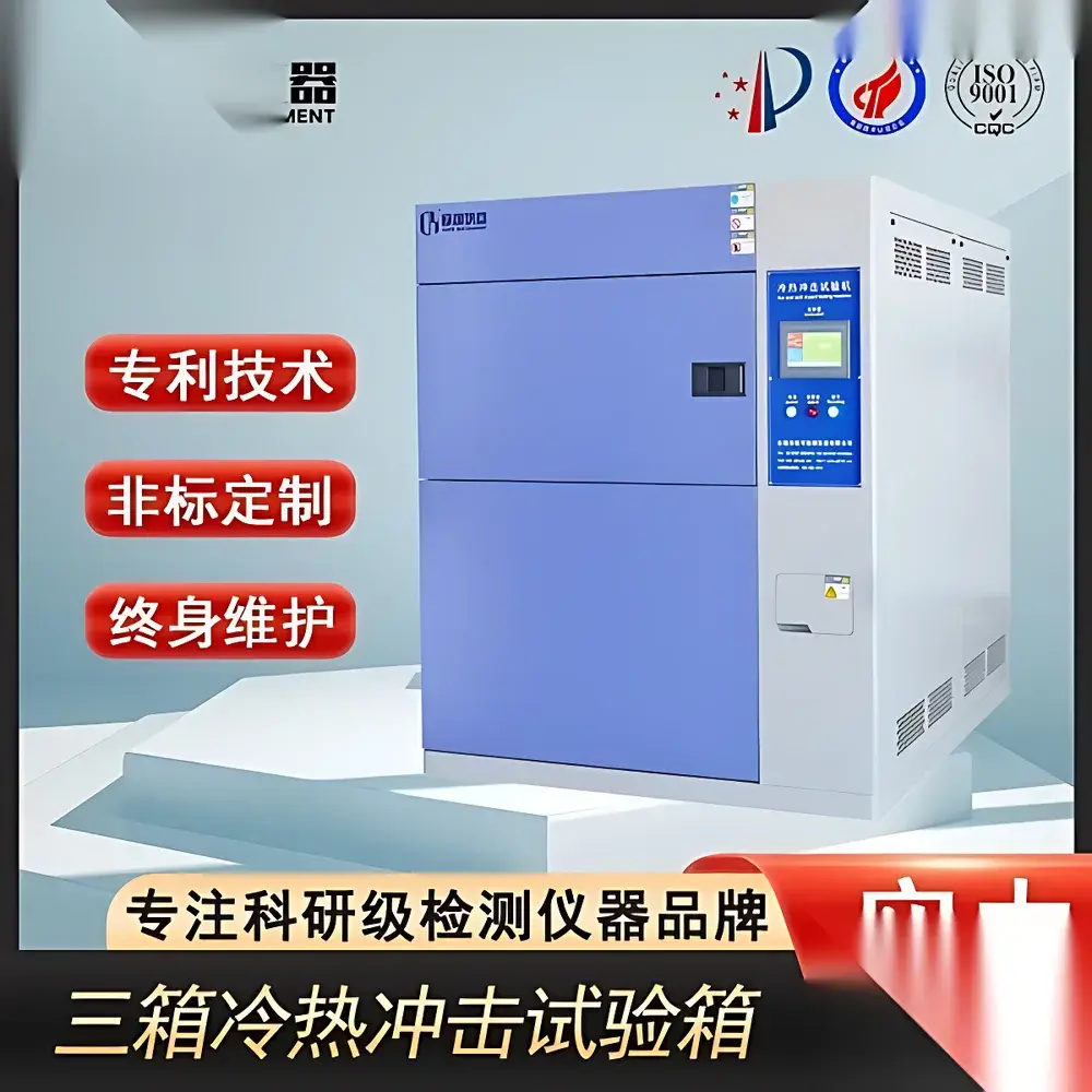
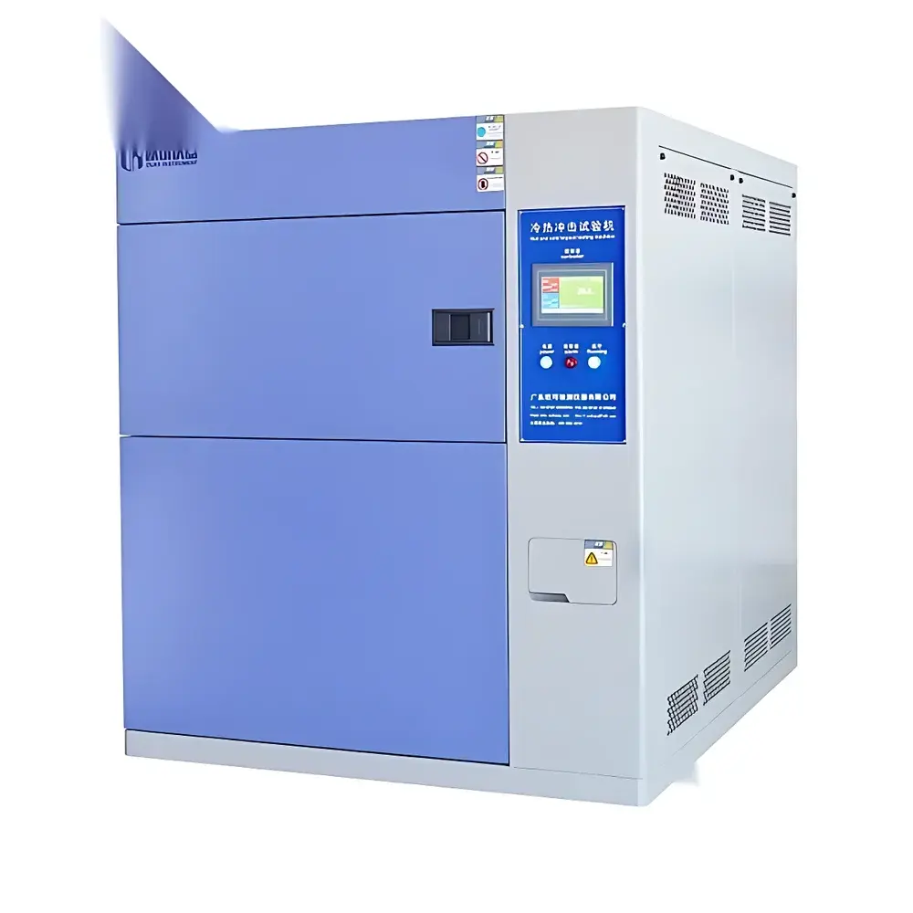
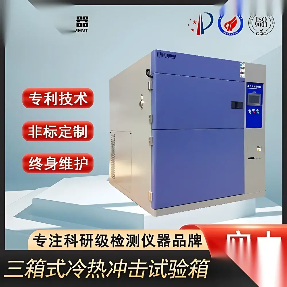
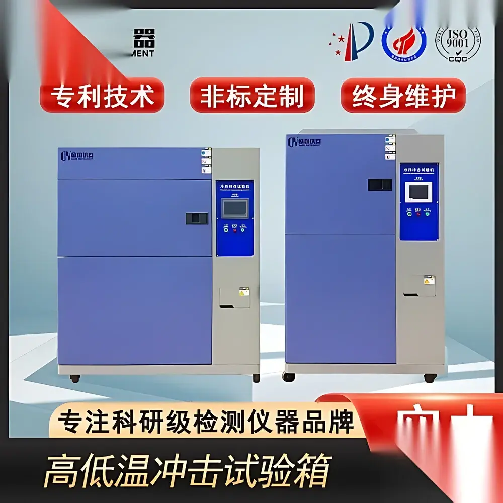
The LED Thermal Shock Test Chamber is a precision-engineered environmental test system designed to evaluate material integrity and structural reliability under rapid, extreme temperature transitions. It operates on the principle of thermal shock testing—subjecting specimens to abrupt shifts between high- and low-temperature environments to accelerate failure mechanisms associated with coefficient-of-thermal-expansion (CTE) mismatch, interfacial delamination, solder joint fatigue, and microcrack propagation. Unlike standard temperature cycling chambers, this unit implements a three-compartment architecture (hot soak chamber, cold soak chamber, and test chamber), enabling true static-sample testing with zero mechanical movement during exposure. This configuration ensures repeatable thermal gradients, eliminates vibration-induced artifacts, and complies with the physical boundary conditions specified in MIL-STD-810H Method 503.5 and IEC 60068-2-14 (Test N: Change of Temperature). The chamber supports both qualification-level stress screening and accelerated life-cycle validation for electronic assemblies, automotive ECUs, aerospace composites, and hermetically sealed optoelectronic packages—including high-brightness LEDs, COB modules, and ceramic substrate-based lighting systems.
Key Features
- Three-zone independent control architecture: separate hot soak (RT to +200 °C), cold soak (RT to −70 °C), and test chamber—ensuring no cross-contamination of thermal mass and eliminating sample displacement errors.
- Dual-stage cascade refrigeration system utilizing semi-hermetic compressors and environmentally compliant refrigerants (R404A for high stage, R23 for low stage), delivering stable sub-zero operation down to −65 °C with ≤5-minute thermal recovery between shocks.
- Pneumatically actuated high-speed damper valves (cycle time <1.2 s) for precise, repeatable air-path switching—maintaining ISO 17025–traceable thermal transition profiles without mechanical jarring.
- High-resolution PID-controlled temperature regulation with ±0.5 °C accuracy and ±2.0 °C uniformity across the full working volume, verified per ASTM E740 and IEC 60068-3-5.
- SUS304 mirror-finish interior surfaces and fire-retardant polyurethane insulation (≥30 mm thickness) minimize thermal lag and prevent condensation-related corrosion or outgassing contamination.
- Configurable electrical feedthroughs (standard 50 mm diameter port), dual-tier stainless steel shelves, and optional data logging interfaces for real-time thermocouple monitoring (J/K/T-type inputs).
Sample Compatibility & Compliance
The chamber accommodates rigid and semi-rigid samples up to 70 × 60 × 60 cm (OK-HH-225 model), including PCBAs, LED modules, battery packs, polymer housings, and metal-ceramic hybrids. Its static-test design avoids centrifugal forces or inertial loading—critical for fragile wire-bonded die and MEMS devices. The system meets full compliance with: IEC 60068-2-14 (Test N), MIL-STD-810H Method 503.5, GJB 150.5A-2009, GB/T 2423.22–2012, QC/T 17–1992 (automotive component endurance), and EIA-364-32 (connector thermal shock). All thermal profiles are programmable and auditable in accordance with FDA 21 CFR Part 11 requirements when paired with validated software (see Software & Data Management section).
Software & Data Management
Equipped with an embedded industrial controller featuring a 7-inch TFT touchscreen HMI, the chamber supports multi-step profile programming (up to 99 segments), real-time graphing of up to 8 thermocouple channels, and automatic report generation (PDF/CSV). Optional Ethernet or RS485 connectivity enables integration into centralized MES or LIMS platforms. When configured with GLP-compliant firmware, the system provides full audit trails—including user login logs, parameter change history, alarm event timestamps, and electronic signatures—meeting ISO/IEC 17025 calibration traceability and GMP documentation standards. Raw thermal data is exportable for post-test Weibull analysis, Arrhenius modeling, and failure mode correlation.
Applications
- Qualification testing of LED packaging substrates (AlN, SiC, FR4) under JEDEC JESD22-A106B thermal shock conditions.
- Reliability screening of automotive ADAS sensors exposed to −40 °C to +125 °C transitions per ISO 16750-4.
- Validation of conformal coating adhesion and solder joint integrity in avionics-grade PCBAs.
- Accelerated aging of lithium-ion battery cells and BMS enclosures under thermal gradient stress.
- Material compatibility assessment for optical lens bonding adhesives subjected to repeated UV-thermal co-stress.
- Process window definition for reflow soldering and die-attach curing in high-power LED manufacturing lines.
FAQ
What distinguishes a three-chamber thermal shock system from a two-chamber (lift-type) design?
A three-chamber system keeps the test specimen stationary while rapidly transferring conditioned air via pneumatic dampers—eliminating mechanical stress, positional drift, and thermal inertia from moving baskets. Two-chamber systems rely on motorized lift mechanisms that introduce vibration, alignment uncertainty, and longer transition times.
Is external cooling water required for operation?
Yes. The dual-stage cascade refrigeration system requires a dedicated closed-loop cooling water supply at 10 m³/h flow rate and ≤32 °C inlet temperature, typically serviced by an external cooling tower. Water quality must meet ASTM D1141 Class II specifications.
Can the chamber be calibrated and certified to ISO/IEC 17025 standards?
Yes—when equipped with NIST-traceable reference thermometers and operated under documented SOPs, third-party accredited labs can issue ISO/IEC 17025 calibration certificates covering temperature uniformity, stability, and transition rate verification.
What safety protections are integrated?
Over-temperature cutoff (dual independent sensors), refrigerant high-pressure shutdown, door interlock, phase-sequence protection, ground fault detection, and emergency stop with mechanical latch—all compliant with IEC 61000-6-2 EMC and IEC 61000-6-4 emission standards.
Is remote monitoring supported?
Standard Ethernet interface supports Modbus TCP and OPC UA protocols; optional cloud gateway enables secure remote access, predictive maintenance alerts, and fleet-wide thermal test analytics via TLS 1.2–encrypted MQTT endpoints.


