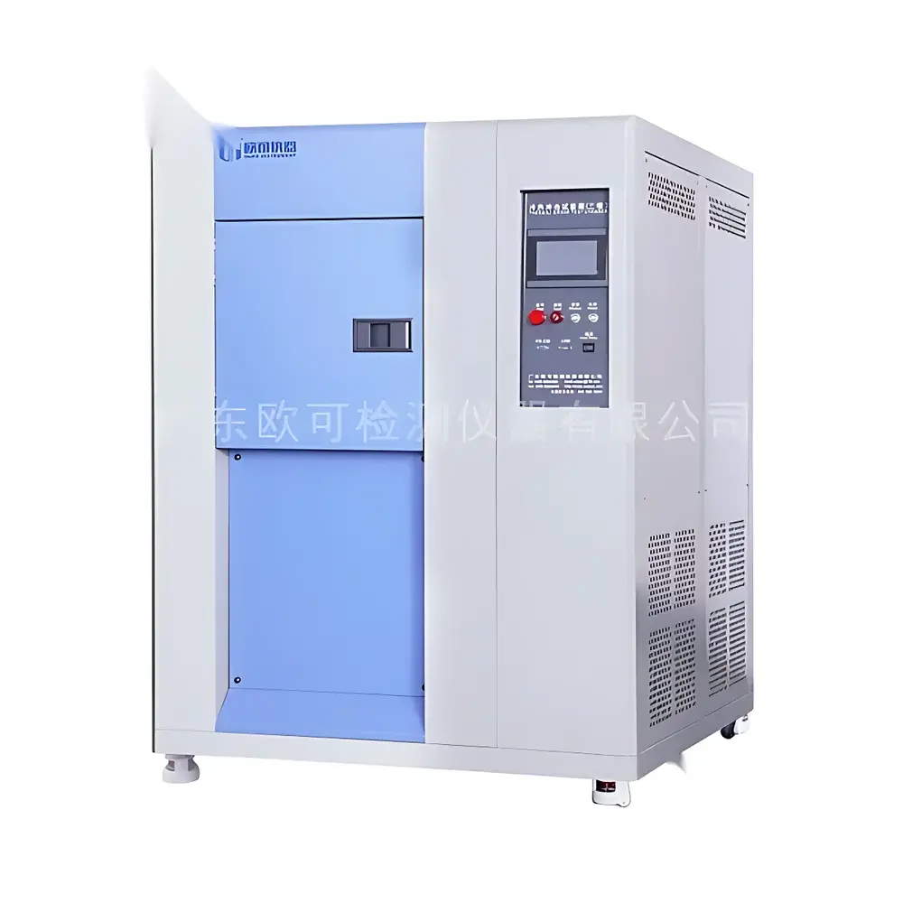
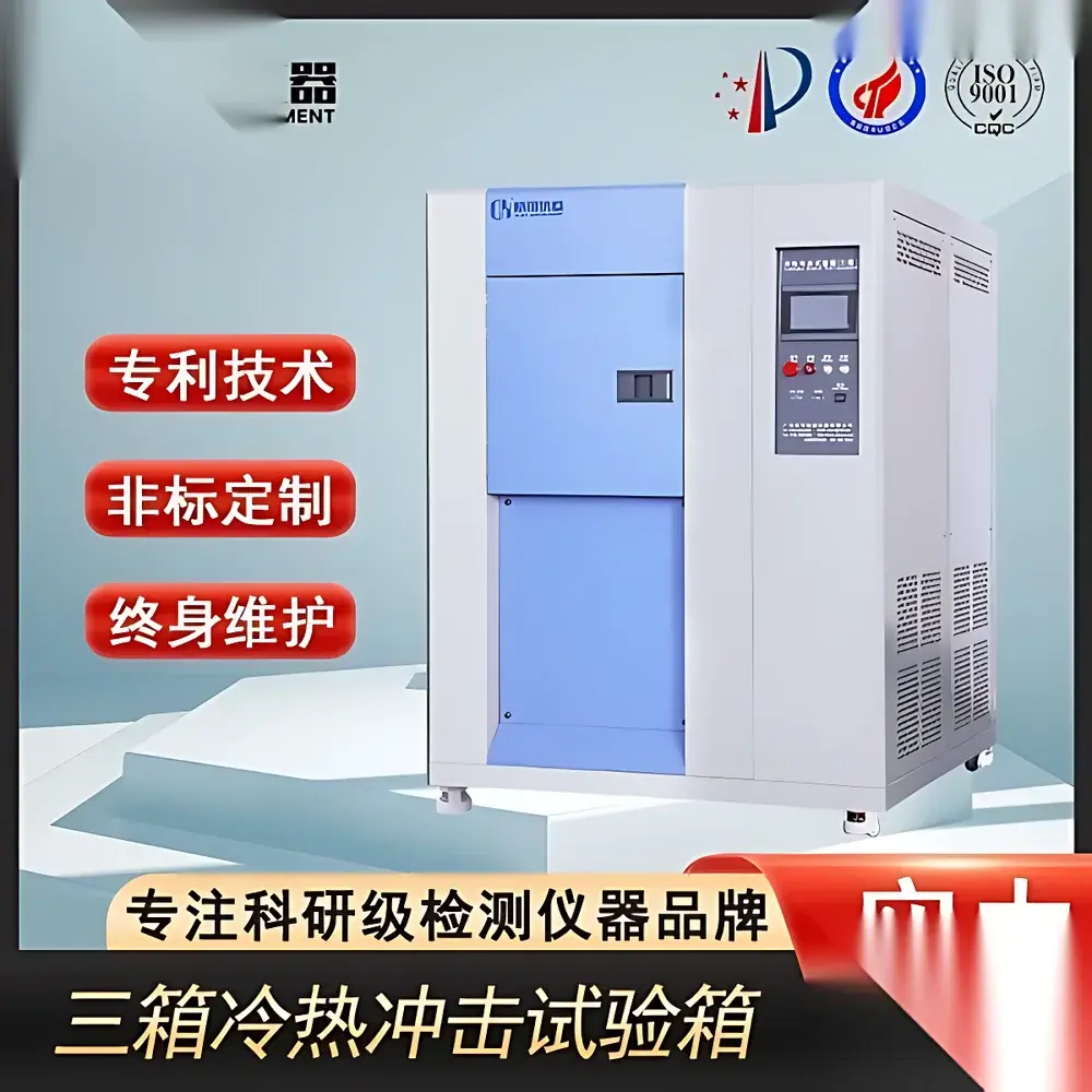
LED Thermal Shock Test Chamber
| [Brand | Other brands |
|---|---|
| Origin | Imported |
| Manufacturer Type | General distributor |
| Price | USD 12,500 (approx.) |
| Internal Dimensions (W×H×D) | 40×35×30 cm to 70×60×60 cm |
| External Dimensions (W×H×D) | 145×180×140 cm to 190×170×270 cm |
| High-Temperature Storage Range | RT to +200°C |
| Low-Temperature Storage Range | RT to –70°C |
| Test Zone Temperature Range | Hot Shock (+60°C to +150°C) |
| Switching Mechanism | Pneumatic damper actuation with stationary test specimen |
| Preheating Time (RT → 150°C) | ~30 min |
| Precooling Time (RT → –70°C) | ~85 min |
| Temperature Recovery Time | <5 min |
| Temperature Control Accuracy | ±0.5°C |
| Temperature Uniformity | ±2.0°C |
| Refrigeration System | Dual-stage cascade refrigeration with semi-hermetic compressors (R404A/R23) |
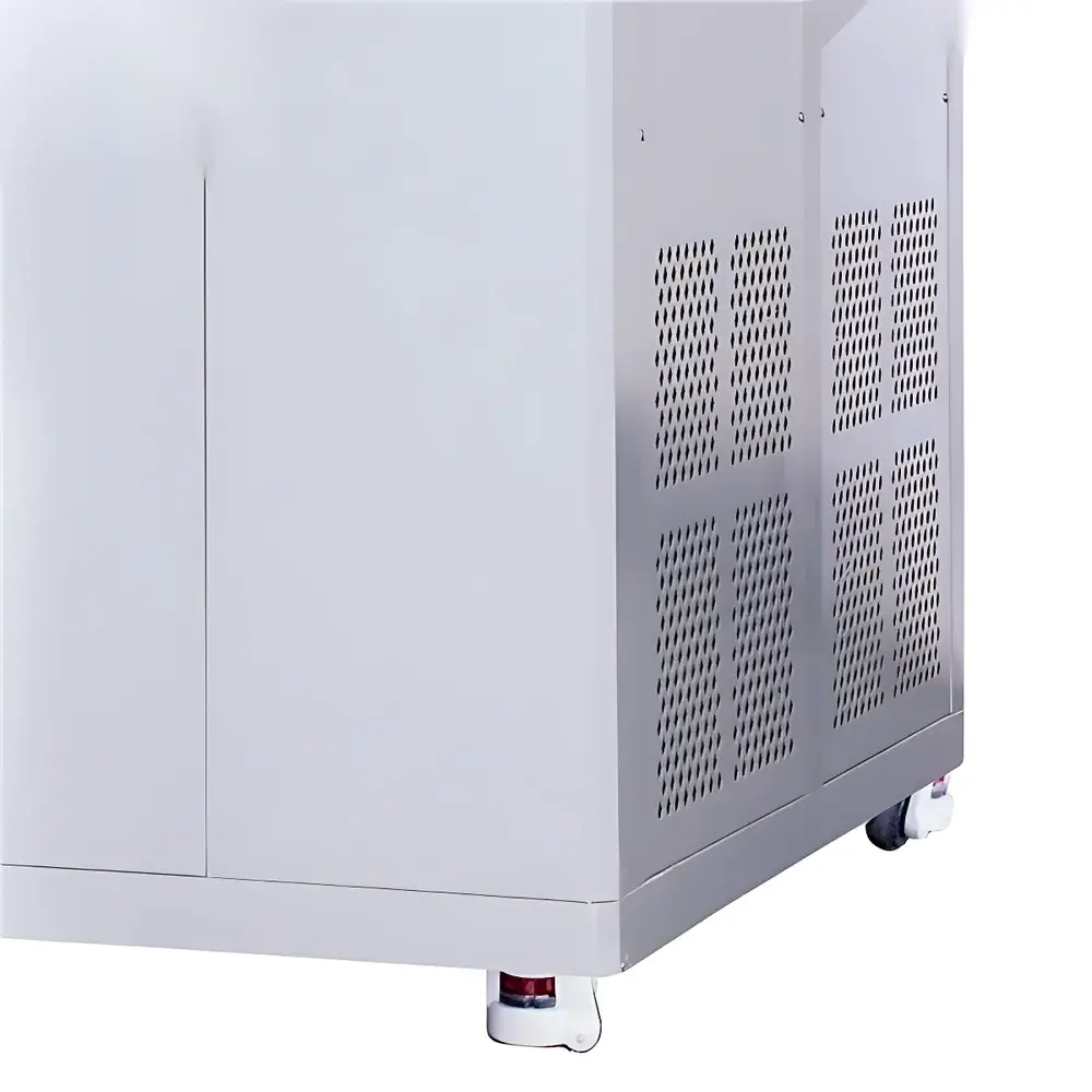
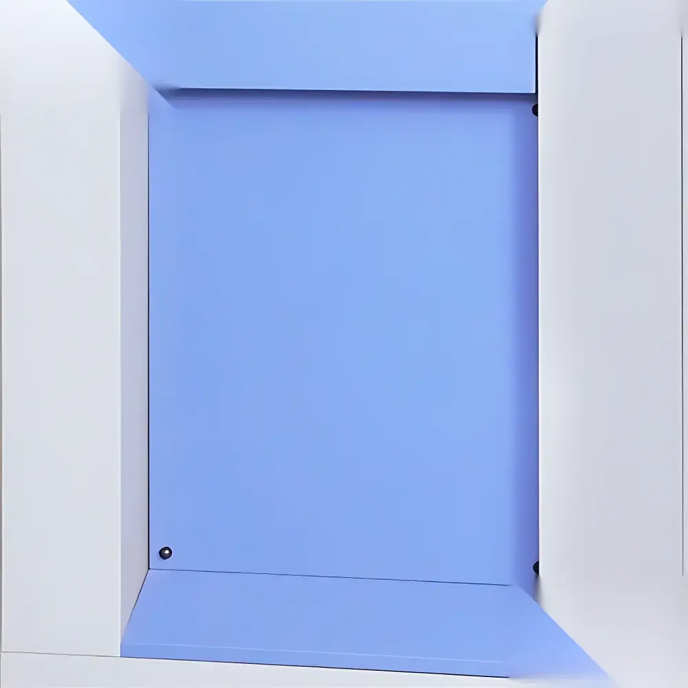
| Inner Chamber Material | SUS#304 mirror-finish stainless steel |
| Outer Chamber Material | SUS#304 stainless steel or powder-coated steel |
| Insulation | High-density fire-retardant PU foam |
| Power Supply | AC 380 V ±5%, 50 Hz ±0.5 Hz, 3-phase 5-wire] |
Overview
The LED Thermal Shock Test Chamber OK-HH Series is an engineered environmental test system designed for rapid thermal cycling evaluation of electronic components—particularly light-emitting diodes (LEDs), PCB assemblies, solder joints, encapsulants, and hybrid packaging—under extreme temperature transitions. It operates on the principle of accelerated thermal stress induction via discrete high-temperature and low-temperature reservoirs, enabling controlled, repeatable exposure to abrupt temperature differentials. Unlike steady-state thermal chambers, this system subjects specimens to transient thermal gradients that simulate real-world operational extremes encountered during power-on/power-off cycles, outdoor deployment, or aerospace mission profiles. The chamber implements a three-zone architecture (hot soak zone, cold soak zone, and test zone), ensuring specimen immobility during exposure—eliminating mechanical vibration artifacts associated with basket-transfer mechanisms. This configuration supports high-fidelity assessment of thermomechanical reliability, interfacial delamination, solder fatigue, and coefficient-of-thermal-expansion (CTE) mismatch failure modes.
Key Features
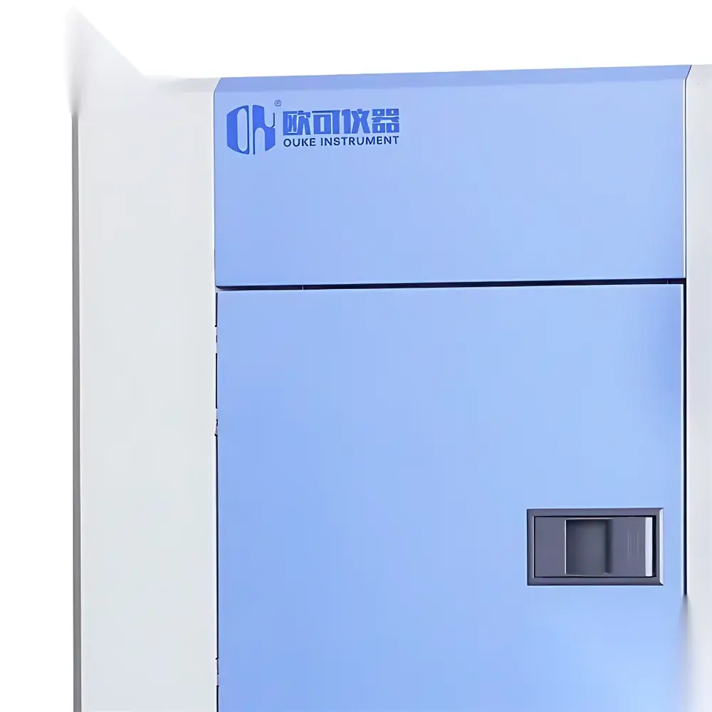
- Three-chamber design with independent hot and cold storage zones and a dedicated stationary test chamber—ensuring zero specimen displacement during thermal transition
- Dual-stage cascade refrigeration system using semi-hermetic compressors and environmentally compliant refrigerants (R404A/R23), optimized for rapid cooldown to –70°C and stable heat-up to +200°C
- Pneumatically actuated high-speed damper system enabling temperature switching in under 5 seconds, with test zone recovery time ≤5 minutes per cycle
- Precision temperature control with ±0.5°C setpoint accuracy and ±2.0°C uniformity across the working volume, validated per IEC 60068-3-5
- SUS#304 mirror-finish stainless steel interior and reinforced PU insulation with fire-retardant certification (UL 94 HF-1 equivalent)
- Configurable cold shock options: –45°C, –55°C, or –65°C base temperature; hot shock range from +60°C to +150°C
- Integrated 50 mm diameter cable port and dual-tier stainless steel sample trays for flexible device mounting and signal routing
- Compliant with industrial cooling infrastructure requirements: water-cooled condenser interface for external 10 m³/h cooling tower (user-supplied)
Sample Compatibility & Compliance
This chamber accommodates LED modules, COB packages, automotive lighting assemblies, power electronics substrates, and optoelectronic sensors up to 70 × 60 × 60 cm (OK-HH-225 model). Its static-test architecture preserves mechanical integrity during cycling—critical for fragile die-attach structures and wire-bonded interconnects. The system meets and exceeds requirements of multiple international and industry-specific standards, including: IEC 60068-2-14 (Test N: Change of Temperature), MIL-STD-810H Method 503.5, GJB 150.5A–2009 (Temperature Shock), GB/T 2423.22–2012 (Temperature Change), and QC/T 17–1992 (Automotive Component Environmental Testing). All thermal profiles are traceable to NIST-calibrated reference sensors, and chamber validation reports support GLP-compliant test documentation workflows.
Software & Data Management
Equipped with an embedded programmable logic controller (PLC) and touchscreen HMI, the chamber supports user-defined thermal shock sequences—including dwell times, ramp rates, cycle counts, and alarm thresholds. Data logging records temperature at ≥1 Hz resolution for both storage zones and test chamber, with timestamped CSV export via USB or Ethernet. Optional software add-ons enable remote monitoring, audit trail generation per FDA 21 CFR Part 11 (electronic signature and change control), and integration into enterprise LIMS or MES platforms via Modbus TCP or OPC UA protocols. Calibration history, maintenance logs, and sensor drift compensation tables are retained onboard for full regulatory traceability.
Applications
- Evaluation of LED package reliability under thermal cycling stress—quantifying lumen depreciation, forward voltage shift, and chromaticity drift
- Qualification testing of conformal coatings, underfill materials, and silicone encapsulants for adhesion loss or microcracking
- Failure analysis of solder joint intermetallic growth and void formation in SMD LED arrays
- Pre-compliance screening for AEC-Q102 (Stress Test Qualification for Discrete Semiconductors) and JEDEC JESD22-A106B (Thermal Shock)
- Validation of thermal interface material (TIM) performance in high-power LED heat sinks
- Environmental stress screening (ESS) for military-grade optoelectronics per MIL-STD-883 Method 1010.8
FAQ
What distinguishes the three-chamber design from two-chamber thermal shock systems?
The three-chamber architecture isolates the test specimen in a stationary chamber while hot and cold reservoirs operate independently—eliminating mechanical stress from moving baskets and improving thermal repeatability.
Is the chamber suitable for testing fully assembled LED luminaires?
Yes—internal dimensions up to 70 × 60 × 60 cm and load capacity up to 50 kg (depending on model) accommodate commercial and industrial LED fixtures with integrated drivers and optics.
Does the system support automated test sequencing and report generation?
Standard PLC-based control enables multi-step profile programming; optional PC software provides automated report generation with pass/fail criteria per test standard clauses.
What cooling infrastructure is required for continuous operation?
A user-provided water-cooled condenser loop with ≥10 m³/h flow rate and ≤32°C inlet temperature is mandatory for sustained operation at extreme temperature setpoints.
How is temperature uniformity verified and maintained?
Uniformity is validated using 9-point sensor mapping per IEC 60068-3-5; real-time PID compensation adjusts refrigerant flow and heater output based on spatial thermal feedback.


")