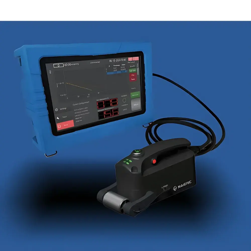
MAIERIC PECT-1 Pulsed Eddy Current Testing System
| Brand | MAIERIC |
|---|---|
| Origin | Anhui, China |
| Model | PECT-1 PULSED EDDY CURRENT |
| Design | Portable |
| Inspection Method | Pulsed Eddy Current (PEC) |
| Signal Type | Transient Electromagnetic Response |
| Measurement Integration | Encoder-based Position Tracking |
| Lift-off Tolerance | Up to 160 mm |
| Wall Thickness Range | 1–30 mm |
| Non-ferromagnetic Cladding Penetration | Up to 2 mm |
| Cladding Thickness Variation Compensation | ±50% with ≤±2% measurement deviation |
| Imaging Mode | User-configurable 2D grid mapping with real-time coordinate registration |
| Compliance | Designed for ASTM E2884-23 (Standard Guide for Pulsed Eddy Current Examination), ISO 12718:2019 (Non-destructive testing — Vocabulary — Eddy current testing), and GLP-aligned data integrity workflows |
Overview
The MAIERIC PECT-1 Pulsed Eddy Current Testing System is an advanced portable NDT instrument engineered for quantitative wall thickness assessment of ferromagnetic metallic structures—particularly carbon steel and stainless steel piping, vessels, and structural components—under intact thermal insulation, weatherproof jackets, or thick paint coatings. Unlike conventional continuous-wave eddy current systems, the PECT-1 employs transient electromagnetic excitation: a high-amplitude, short-duration current pulse is applied to a broadband excitation coil, generating a rapidly decaying primary magnetic field. According to Faraday’s law of induction and Lenz’s law, this time-varying field induces depth-penetrating eddy currents in the conductive substrate. The decay profile of the secondary magnetic field—measured by a separate sensing coil—is directly modulated by material conductivity, magnetic permeability, geometry, and, critically, wall thickness. Thicker sections exhibit slower field decay due to greater current path volume and lower resistive dissipation; thinner or corroded regions accelerate decay. This physics-based relationship enables absolute thickness estimation without direct surface contact or cladding removal.
Key Features
- True lift-off robustness: Engineered for operational stability at lift-off distances up to 160 mm—enabling inspection through thick insulation layers, air gaps, or irregular jacketing without signal nulling or recalibration.
- Dual-material capability: Switchable excitation and signal processing modes support accurate thickness quantification on both carbon steel (high permeability) and austenitic stainless steel (low permeability, higher conductivity), eliminating need for hardware swaps.
- Encoder-synchronized 2D corrosion mapping: Integrated high-resolution optical encoder captures sub-millimeter positional data, enabling precise georeferencing of each thickness measurement point. Users define custom grid resolution (e.g., 2 × 2 mm to 25 × 25 mm), with real-time pixel-by-pixel thickness rendering using intuitive color gradients (e.g., blue = nominal, red = critical thinning).
- Dynamic cladding compensation: Real-time monitoring of insulation thickness variation (±50% relative to baseline) with automatic signal correction; system reports lift-off grade and validity flag per measurement point in accordance with ASTM E2884 Annex A3 guidelines.
- Multi-mode acquisition: Supports single-point spot measurement, time-triggered periodic sampling, user-defined grid scanning, and continuous encoder-driven profiling—all requiring only one initial calibration against a reference standard block.
Sample Compatibility & Compliance
The PECT-1 is validated for use on ferromagnetic and non-ferromagnetic conductive substrates, including ASTM A106/A53 carbon steel pipe, ASTM A312 stainless steel tubing, and welded pressure vessel plates. It complies with the physical measurement principles defined in ISO 12718:2019 and follows methodology guidance in ASTM E2884-23 for pulsed eddy current examination of insulated pipelines. All measurement data—including raw decay waveforms, position stamps, environmental metadata (temperature, battery level), and operator ID—are timestamped and stored in encrypted binary format compliant with ALCOA+ principles (Attributable, Legible, Contemporaneous, Original, Accurate, Complete, Consistent, Enduring, Available). Audit trails support GLP and GMP-aligned quality systems.
Software & Data Management
The embedded 2K capacitive touchscreen interface runs MAIERIC’s proprietary PECTView firmware, optimized for glove-compatible operation and low-glare outdoor visibility. Measurement sessions are saved as project files containing waveform datasets, encoded positional logs, and annotated imaging matrices. Export options include CSV (for Excel/Python analysis), PNG/JPEG (annotated heatmaps), and XML (structured metadata for integration with CMMS platforms such as SAP PM or IBM Maximo). Firmware supports secure over-the-air updates and role-based access control (operator, technician, administrator). All data exports retain full traceability: no loss of original sample rate (≥1 MHz digitization), no interpolation, no compression artifacts.
Applications
- In-service inspection of insulated hydrocarbon pipelines in refineries and petrochemical plants without shutdown or insulation removal.
- Corrosion under insulation (CUI) screening on steam headers, boiler feedwater lines, and flare systems.
- Wall loss assessment of aboveground storage tank shells beneath aluminum or fiberglass cladding.
- Verification of post-weld heat treatment (PWHT) integrity where residual stress affects local permeability—and thus PEC decay kinetics.
- Baseline thickness surveys for RBI (Risk-Based Inspection) programs per API RP 580 requirements.
FAQ
What standards does the PECT-1 comply with for field NDT reporting?
It aligns with ASTM E2884-23 methodology, ISO 12718:2019 terminology, and supports documentation requirements for ASME B31.4/B31.8 and API RP 570 compliance audits.
Can the system distinguish between general corrosion and localized pitting?
While PEC provides average thickness over its effective footprint (typically Ø25–50 mm depending on lift-off), combined use of high-resolution grid mapping and trend analysis across adjacent pixels enables identification of localized thinning anomalies exceeding ±15% deviation from neighboring points.
Is probe calibration required before each inspection?
No—only a single reference calibration using a known-thickness standard block is needed per probe type; the system maintains calibration stability across ambient temperature ranges from −10 °C to +50 °C.
Does the software support automated report generation?
Yes—customizable PDF reports include cover page, equipment ID, inspection date/time, operator credentials, summary heatmap, statistical thickness distribution (min/mean/max/std dev), and annotated cross-section views—all exportable with digital signature fields.
How is data integrity ensured during long-duration scans?
All waveform and positional data are written to non-volatile flash memory in real time with cyclic redundancy checksum (CRC-32); power interruption recovery preserves all successfully committed measurements up to the last write cycle.


