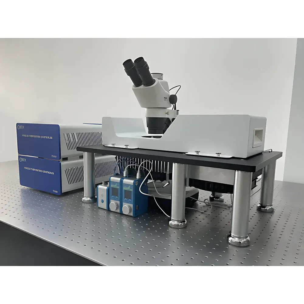
Microblox MSTC Microfluidic Temperature-Controlled Microscopy Station
| Brand | Microblox |
|---|---|
| Origin | France |
| Model | MSTC |
| Core Components | Fluigent Flow EZ Pressure Pump, Flow Unit Mass Flow Sensor, Metal-Based Thermal Control Stage |
| Temperature Range | Customizable (Typically −40 °C to +120 °C) |
| Microscope Compatibility | Standard Inverted & Upright Microscopes (via Open-Top Chip Mounting Interface) |
| Structural Frame | Steel-Aluminum Hybrid Laboratory Workbench (Single-Sided Configuration) |
| Compliance | CE Marked, RoHS Compliant, Designed for ISO/IEC 17025-Compatible Lab Environments |
Overview
The Microblox MSTC Microfluidic Temperature-Controlled Microscopy Station is an integrated platform engineered for precise spatiotemporal control and real-time optical observation of microfluidic processes under dynamically regulated thermal conditions. Built upon Couette-based fluid handling principles and conductive thermal management architecture, the system enables reproducible execution of experiments requiring stable temperature gradients across microchannels—critical for studies in cryogenic droplet formation, thermally triggered hydrogel polymerization, phase-transition kinetics, and live-cell response assays under thermal stress. Unlike conventional benchtop setups relying on ambient or Peltier-only regulation, the MSTC employs direct metal-to-fluid-path thermal coupling via machined aluminum/copper manifolds, minimizing thermal lag and ensuring sub-second response times to setpoint changes. Its open-top chip mounting interface is mechanically decoupled from actuation and thermal subsystems, preserving optical path stability during long-duration time-lapse imaging.
Key Features
- Modular thermal control stage with programmable range from −40 °C to +120 °C (custom extended ranges available), achieving ±0.001 °C setpoint stability over 24 h (verified per IEC 60068-3-5)
- Fluigent Flow EZ pressure-driven microfluidic pump: dual-channel, 0–2000 mbar output, <0.1% flow fluctuation at constant pressure mode; compatible with organic solvents and aqueous media
- Integrated Flow Unit mass flow sensor: calibrated for 0.01–1000 µL/min full-scale range, NIST-traceable accuracy ±1.5% of reading
- Open-access chip holder with kinematic alignment pins and vacuum-assisted clamping—designed for standard glass/silicon/PDMS chips (up to 75 × 25 mm footprint)
- Steel-aluminum hybrid structural frame compliant with EN 14727 laboratory furniture standards; single-sided configuration optimized for integration into ISO Class 5–7 cleanroom workflows
- EMI-shielded electronics enclosure with redundant thermal cutoffs and pressure relief valves meeting EN 61000-6-2/6-4 immunity requirements
Sample Compatibility & Compliance
The MSTC accommodates a broad spectrum of microfluidic substrates—including fused silica, borosilicate glass, silicon wafers, and oxygen-plasma-bonded PDMS devices—without compromising thermal uniformity or mechanical integrity. Chip mounting interfaces support both passive capillary and active pressure-driven operation modes. All wetted materials comply with USP Class VI biocompatibility standards and FDA 21 CFR 177.2600 for repeated-use fluid contact. System-level validation documentation includes IQ/OQ protocols aligned with GLP and GMP Annex 11 expectations, supporting audit readiness for pharmaceutical process development labs. Full traceability of critical components (e.g., Fluigent pump serial numbers, thermal sensor calibration certificates) is maintained within the device logbook.
Software & Data Management
Control is executed via Microblox’s MSTC Control Suite (v3.2+), a Windows-based application supporting synchronized parameter logging at up to 100 Hz sampling rate across pressure, flow, temperature, and external trigger inputs. The software implements role-based user access control (RBAC), electronic signatures, and full audit trail functionality compliant with FDA 21 CFR Part 11 requirements. Experimental metadata—including chip ID, protocol version, operator ID, and environmental timestamping—is embedded directly into exported TIFF/AVI files. Raw data exports are structured in HDF5 format, enabling direct ingestion into MATLAB, Python (via h5py), or commercial analysis platforms such as ImageJ/Fiji and Imaris.
Applications
- Droplet-based microreactors: monodisperse emulsion generation under sub-zero nucleation conditions
- Organ-on-chip thermal challenge assays: endothelial barrier function evaluation during hyperthermic exposure (39–42 °C)
- Cryopreservation process optimization: vitrification kinetics mapping using fluorescent phase indicators
- Thermoresponsive hydrogel characterization: swelling/deswelling dynamics monitored via confocal reflection contrast
- High-throughput drug cytotoxicity screening: temperature-gated release of therapeutics from lipid nanocarriers
- Microscale crystallization studies: polymorph selection control via ramped cooling profiles (−0.1 to +5 °C/min)
FAQ
Is the MSTC compatible with upright and inverted microscope configurations?
Yes—the open-top chip mount provides unobstructed 0°–90° objective access and supports both transmitted-light and epi-fluorescence modalities without optical path modification.
Can the system be validated for GxP-regulated environments?
Yes—full qualification packages (DQ/IQ/OQ/PQ) are available upon request, including calibration records traceable to national metrology institutes and deviation reporting templates.
What is the maximum allowable chip thickness for stable thermal coupling?
Standard holders accommodate chips up to 2.0 mm thick; custom inserts are available for thicker substrates (e.g., quartz cuvettes) with recalibrated thermal transfer coefficients.
Does the system support third-party pump integration?
Yes—RS-485 and analog 0–10 V I/O ports enable synchronization with external syringe pumps or electrokinetic drivers, provided they conform to IEC 61000-4-5 surge immunity class 3.
How is temperature uniformity verified across the chip surface?
Each unit undergoes IR thermography mapping (FLIR A655sc) at five representative setpoints; spatial deviation is reported in the factory acceptance test report (FATR) and remains ≤±0.05 °C over 10 × 10 mm active area.


