Olympus Ultrasonic Testing System for Large Wind Turbine Roller Inspection
| Brand | Olympus |
|---|---|
| Origin | Shanghai, China |
| Manufacturer Type | Authorized Distributor |
| Product Origin | Domestic (China) |
| Model | Custom-Engineered UT System for Wind Turbine Rollers |
| Pricing | Available Upon Request |
| Application Domain | Wind Energy Component Quality Assurance |
| Channel Capacity | Up to 4 Channels |
| Inspection Method | Equivalent Flat-Bottom Hole (FBH) Sizing |
| Sensitivity | 0.5 mm × 0.5 mm FBH |
| Probe Interface | Conventional UT & Phased Array UT Compatible |
| Automation Integration | Robotic Arm / Overhead Crane + Vision-Based Loading/Unloading |
| Software | Proprietary Real-Time UT Platform with Offline CAD-Based Path Planning, Zonal Defect Classification (Functional vs. Non-Functional Zones), AI-Assisted Defect Recognition, Auto-Report Generation, Remote Supervisory Control, and MES/ERP System Interfacing |
| Compliance Framework | Designed to Support ISO 10893-2, ASTM E273, EN 12681, and GLP/GMP-aligned audit trail requirements |
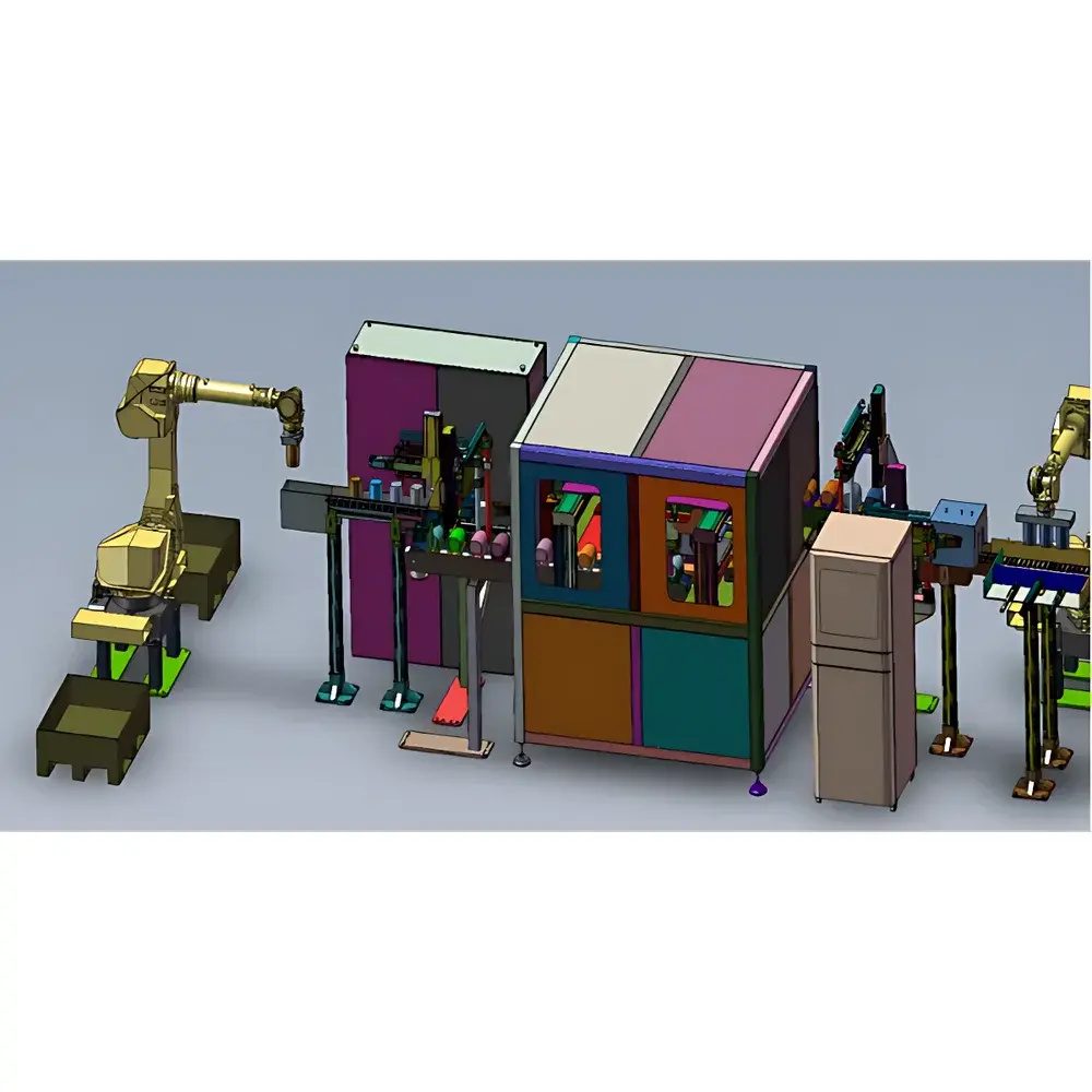
Overview
The Olympus Ultrasonic Testing System for Large Wind Turbine Roller Inspection is a purpose-built, high-integrity non-destructive testing (NDT) platform engineered for the automated volumetric inspection of large-diameter cylindrical roller components used in wind turbine main shaft and pitch/yaw bearings. Leveraging pulse-echo ultrasonic principles—specifically through time-of-flight diffraction (TOFD) and phased array ultrasonic testing (PAUT)—this system delivers repeatable, traceable, and metrologically sound flaw detection in bearing-grade steels such as AISI 52100, 100Cr6, and equivalent high-carbon chromium alloys. Unlike generic UT systems, this configuration integrates material-specific velocity calibration, attenuation compensation algorithms, and geometry-adaptive focusing to maintain sensitivity across complex curved surfaces and variable wall thicknesses typical of forged rollers ranging from Ø300 mm to Ø1200 mm in diameter and up to 1500 mm in length.
Key Features
- Multi-channel architecture supporting up to four independent UT channels—enabling simultaneous A-scan acquisition, sectorial scanning (S-scan), and C-scan imaging without hardware reconfiguration.
- Modular mechanical integration interface compatible with industrial robotic arms (e.g., KUKA, ABB) or overhead gantry cranes equipped with machine vision guidance for precise part centering, orientation verification, and zero-contact loading/unloading.
- Fully proprietary software suite built on a deterministic real-time operating layer; supports customizable UI layouts, role-based access control, and configurable pass/fail logic per inspection zone.
- Defect classification engine trained on metallurgical failure modes common in wind turbine rollers—including subsurface inclusions, quench cracks, forging laps, and grinding burns—with automated distinction between functional surface zones (e.g., raceway contact bands) and non-functional structural zones (e.g., fillets, shoulders).
- Offline simulation module accepts STEP or IGES CAD models to generate collision-free, curvature-compensated scanning trajectories—reducing setup time by >65% versus manual teach-in methods.
- Secure remote operation via TLS-encrypted web interface; enables live waveform streaming, parameter adjustment, and report review from offsite engineering centers or QA oversight teams.
- Native OPC UA and RESTful API support ensures bi-directional data exchange with Manufacturing Execution Systems (MES), ERP platforms (e.g., SAP), and digital twin infrastructure for closed-loop quality analytics.
Sample Compatibility & Compliance
This system is validated for use with forged and heat-treated bearing steel components meeting ASTM A295, DIN 17230, and GB/T 18254 specifications. It accommodates both longitudinal and transverse inspection orientations, with probe coupling optimized for water-immersion and bubbler-based scanning configurations. All measurement protocols adhere to ISO 10893-2 (non-destructive testing of steel tubes), ASTM E273 (standard practice for ultrasonic examination of pipe and tubing), and EN 12681 (non-destructive testing of castings—ultrasonic testing). The software architecture incorporates full 21 CFR Part 11-compliant electronic signatures, audit trails, and data integrity safeguards required for GLP/GMP-regulated manufacturing environments.
Software & Data Management
The embedded inspection software provides full lifecycle data handling—from raw RF signal capture and envelope detection to post-processing visualization, statistical analysis, and regulatory reporting. Each inspection record includes timestamped waveform archives, calibrated gain settings, probe characterization files, and geometric correction matrices. Reports are exportable in PDF/A-2b, XML, and CSV formats, with optional integration into enterprise document management systems (EDMS). All software updates follow IEC 62304-compliant development practices, with version-controlled release notes and validation documentation available upon request.
Applications
- Final acceptance testing of large-diameter tapered and cylindrical rollers prior to bearing assembly.
- In-process monitoring during heat treatment and grinding operations to detect microstructural anomalies.
- Root cause analysis of field-failed components through comparative baseline scanning and defect morphology mapping.
- Supplier qualification audits requiring objective, operator-independent evaluation criteria.
- Supporting ISO 55001 asset management frameworks by linking inspection outcomes to remaining useful life (RUL) estimation models.
FAQ
Does this system support both conventional UT and phased array UT probes?
Yes—hardware architecture includes dual-mode pulser-receiver modules compatible with standard single-element transducers and matrix/array probes up to 128 elements.
Can the software distinguish between surface-breaking and subsurface defects?
Yes—through combined TOFD + PAUT mode fusion and depth-gated amplitude analysis, it classifies defect location relative to the near-field zone and surface topology.
Is offline path planning limited to CAD models, or does it accept point-cloud data?
The current version accepts native CAD formats (STEP, IGES); point-cloud import (e.g., STL, OBJ) is supported via optional add-on module with mesh-to-CAD conversion.
How is calibration traceability maintained across shifts and operators?
Calibration status is embedded in every inspection file using NIST-traceable reference standards (e.g., IIW Block, V1 Block), with automatic logging of calibration date, technician ID, and environmental parameters.
What cybersecurity measures are implemented for remote access?
Remote sessions enforce multi-factor authentication (MFA), session timeouts, encrypted data-in-transit (AES-256/TLS 1.3), and configurable IP whitelisting—all compliant with IEC 62443-3-3 Level 2 requirements.


